Out with the old… in with the new..

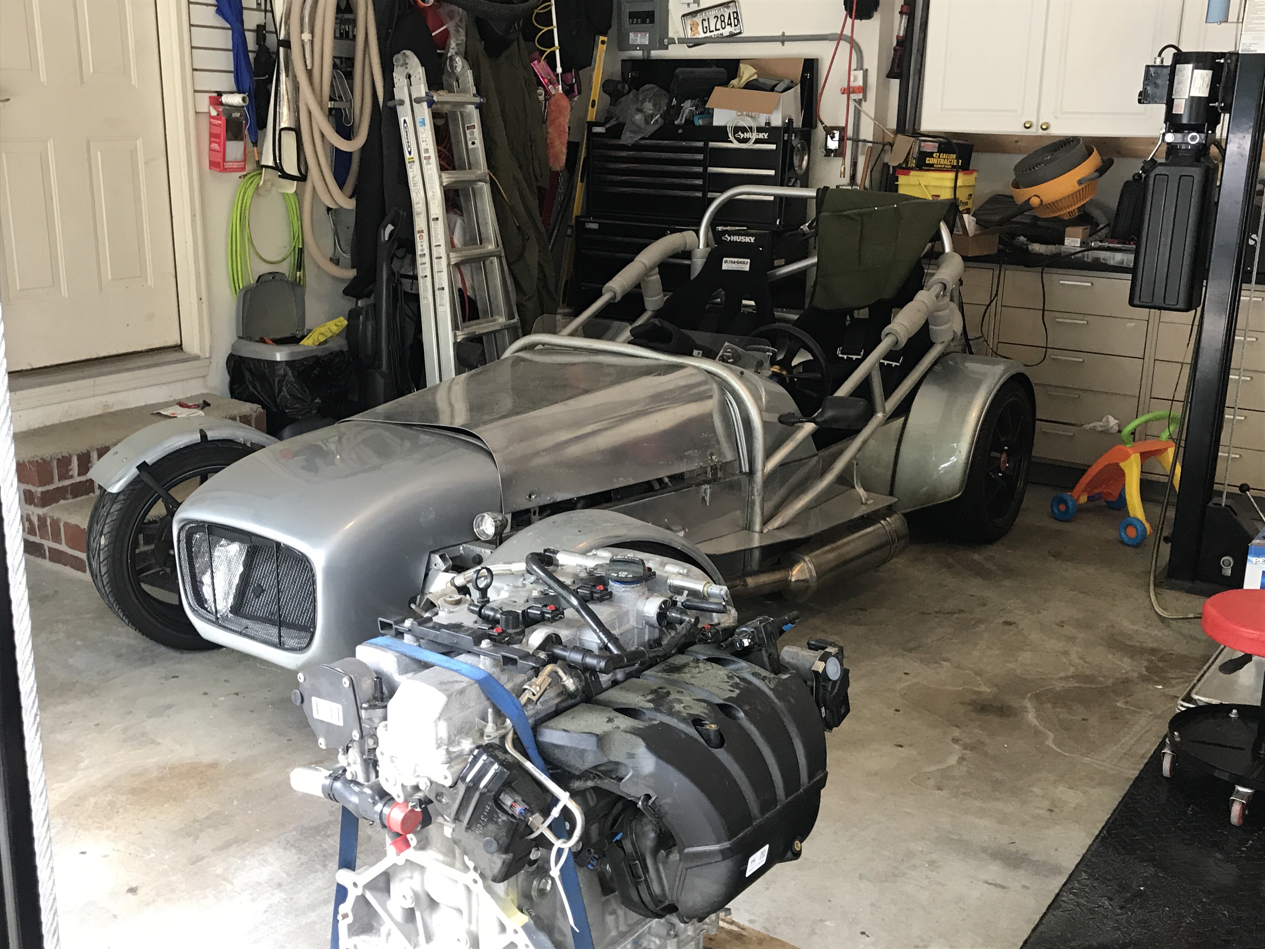
The work to remove the motor and transmission was fairly straight forward 

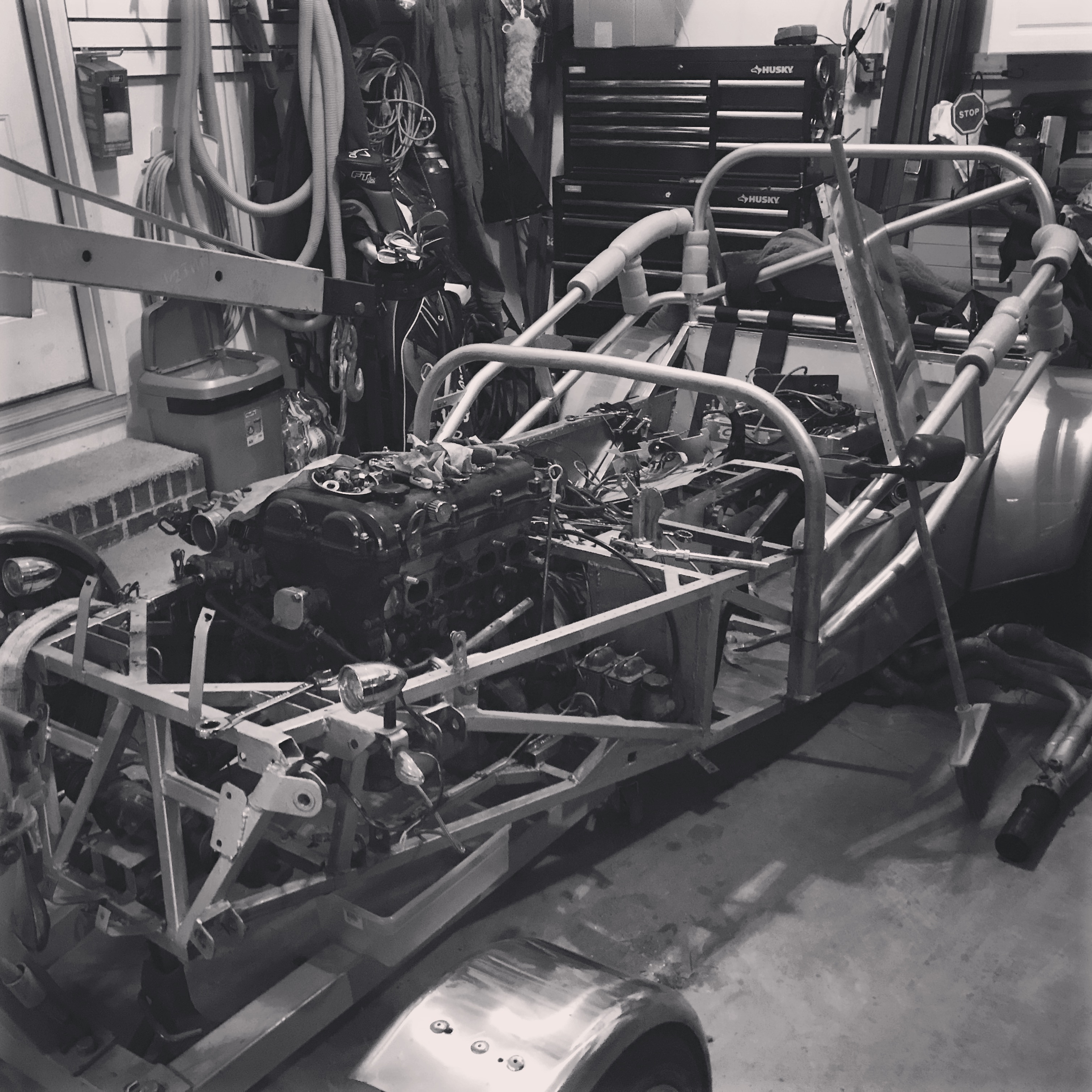
I removed the body panels on the front,the scuttle, nose, hood, side panel, dashboard etc and then removed the exhaust exposing the engine.

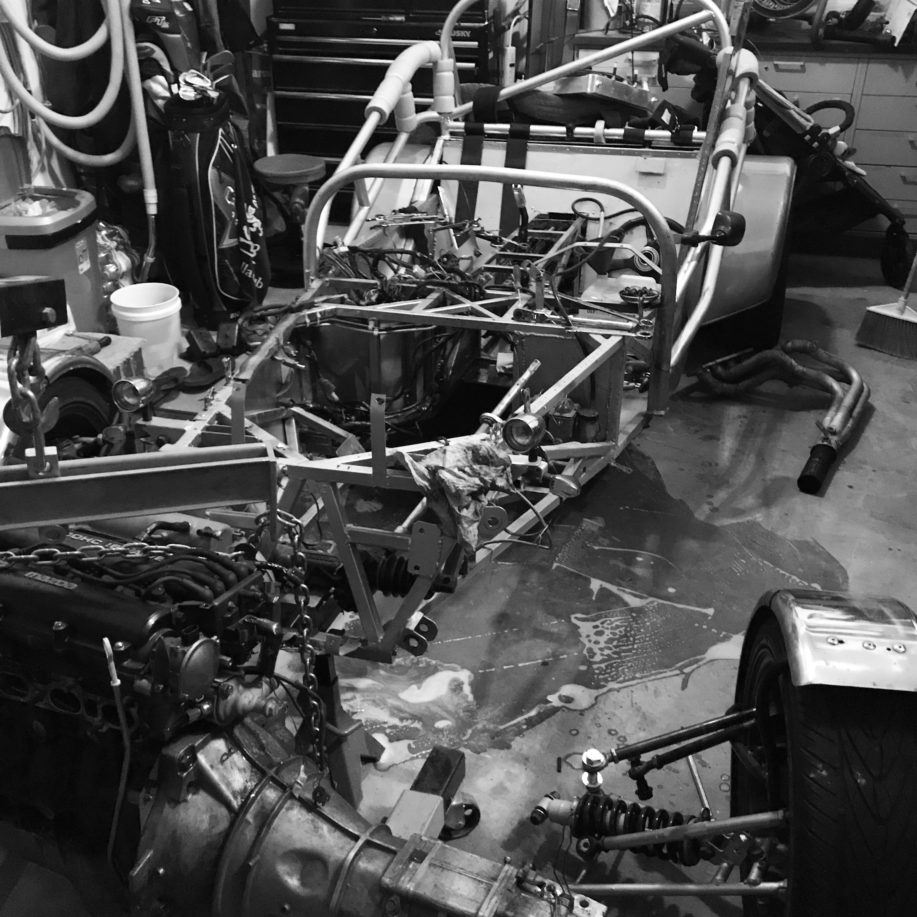
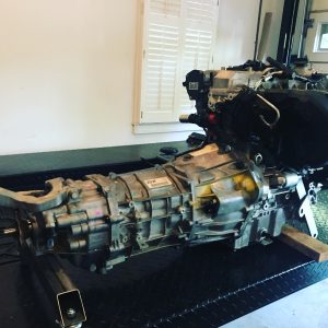
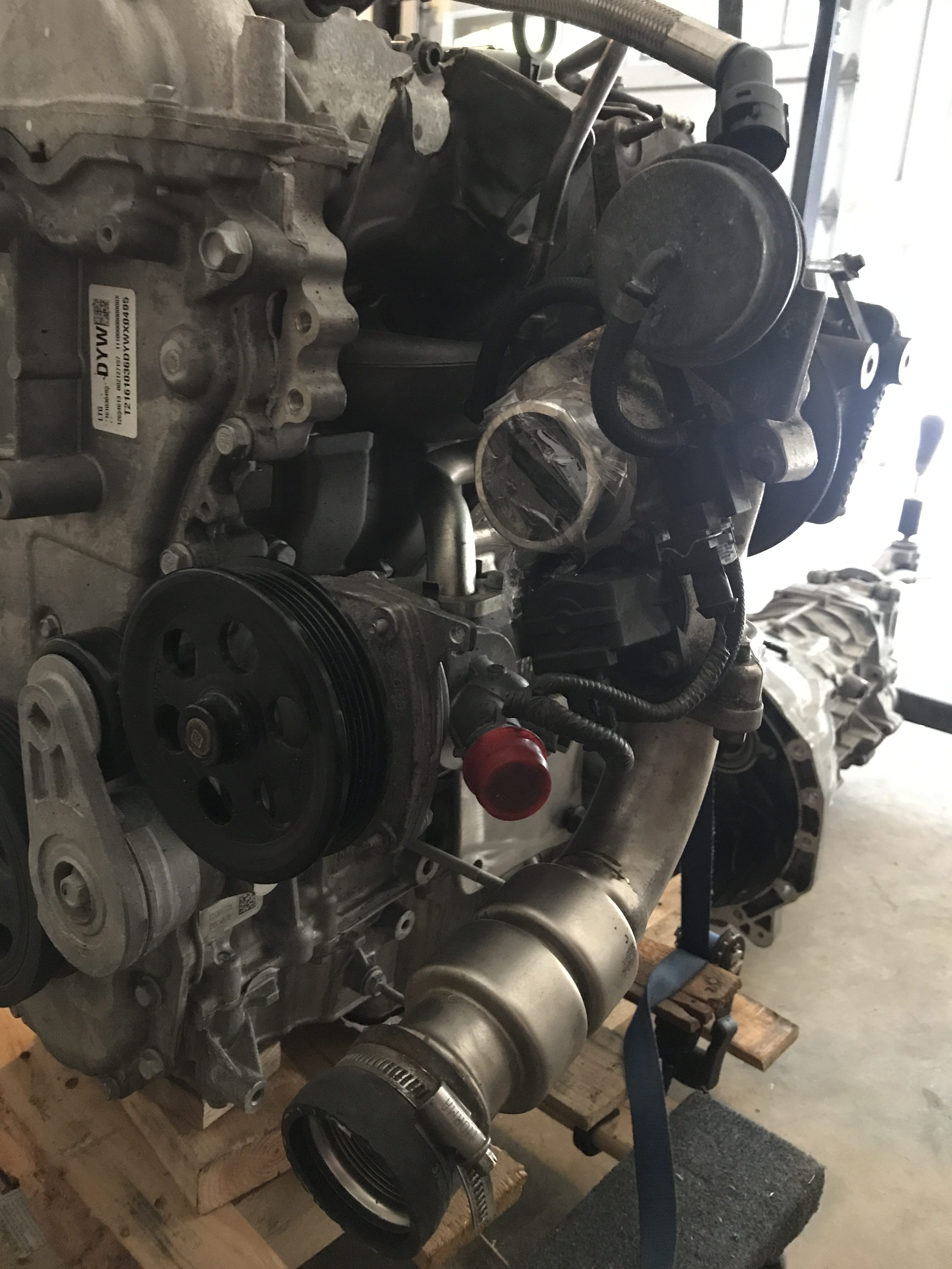
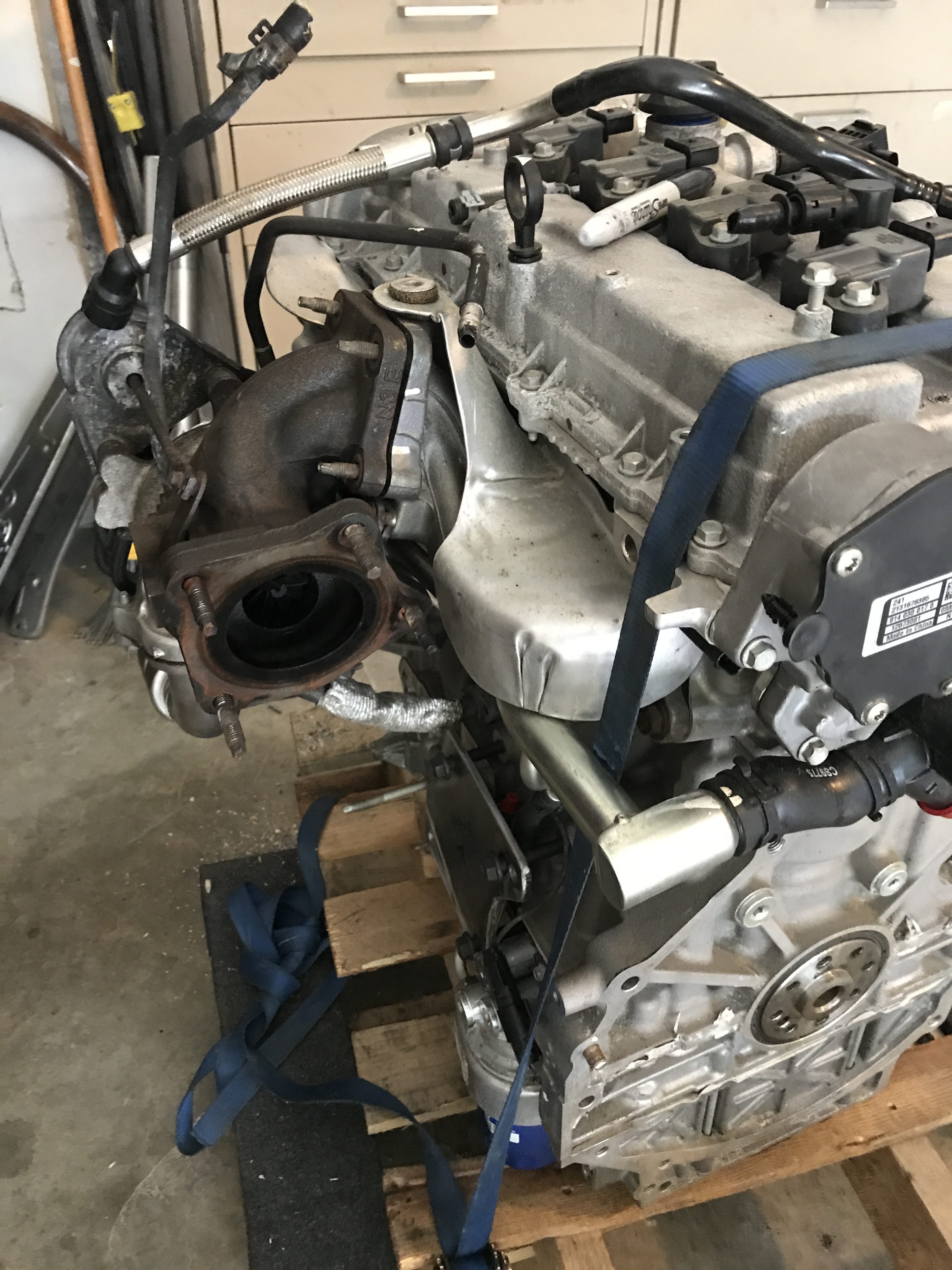
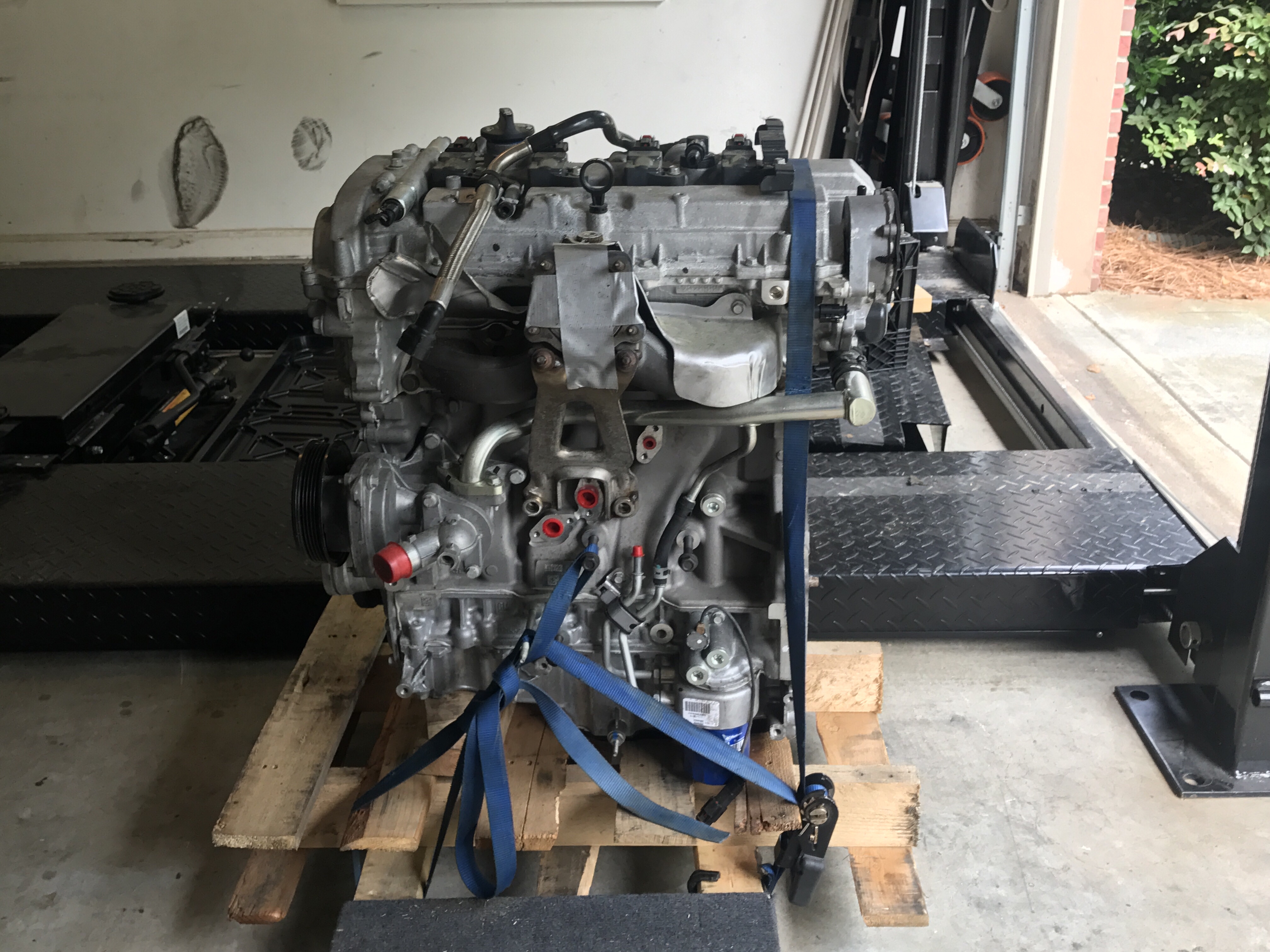
Up next- we pulled the engine (Drain all of the fluids before ever pulling an engine..) and made a big mess.  Shockingly it came out quite easily.

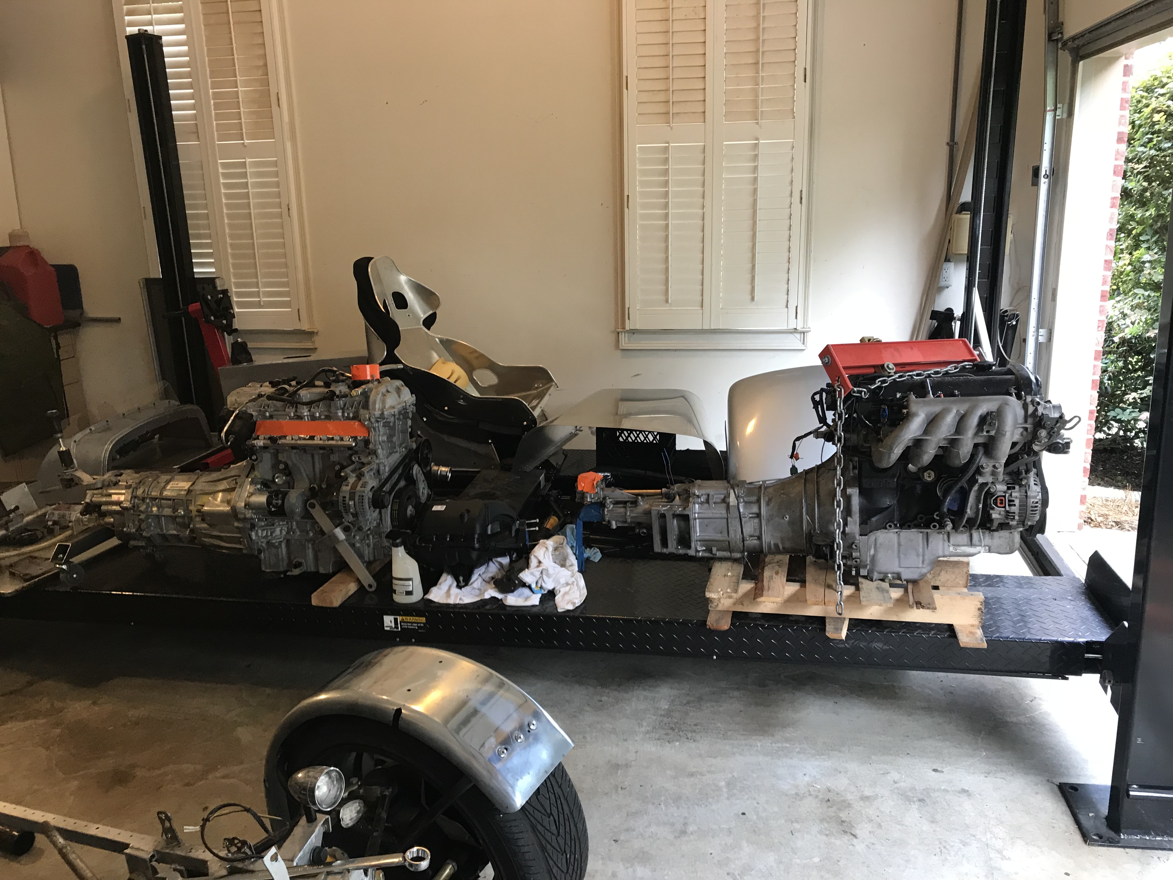
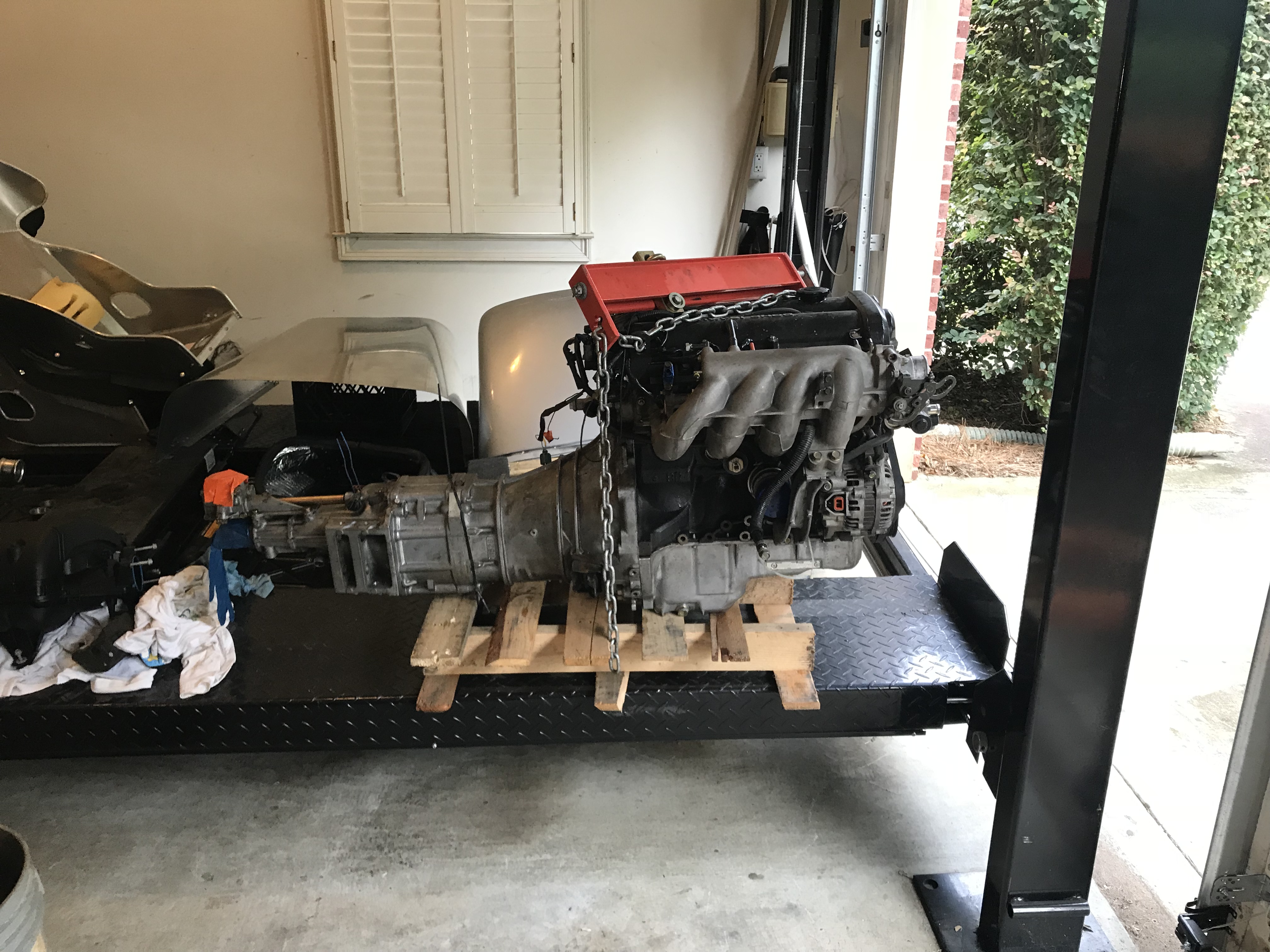
On the left- The ecotec engine.  On the right- The Miata engine. (note the miata engine is on a pallet which lifts the height.  The transmission on the ecotec is about 2″ shorter so the shifting location isn’t idea.

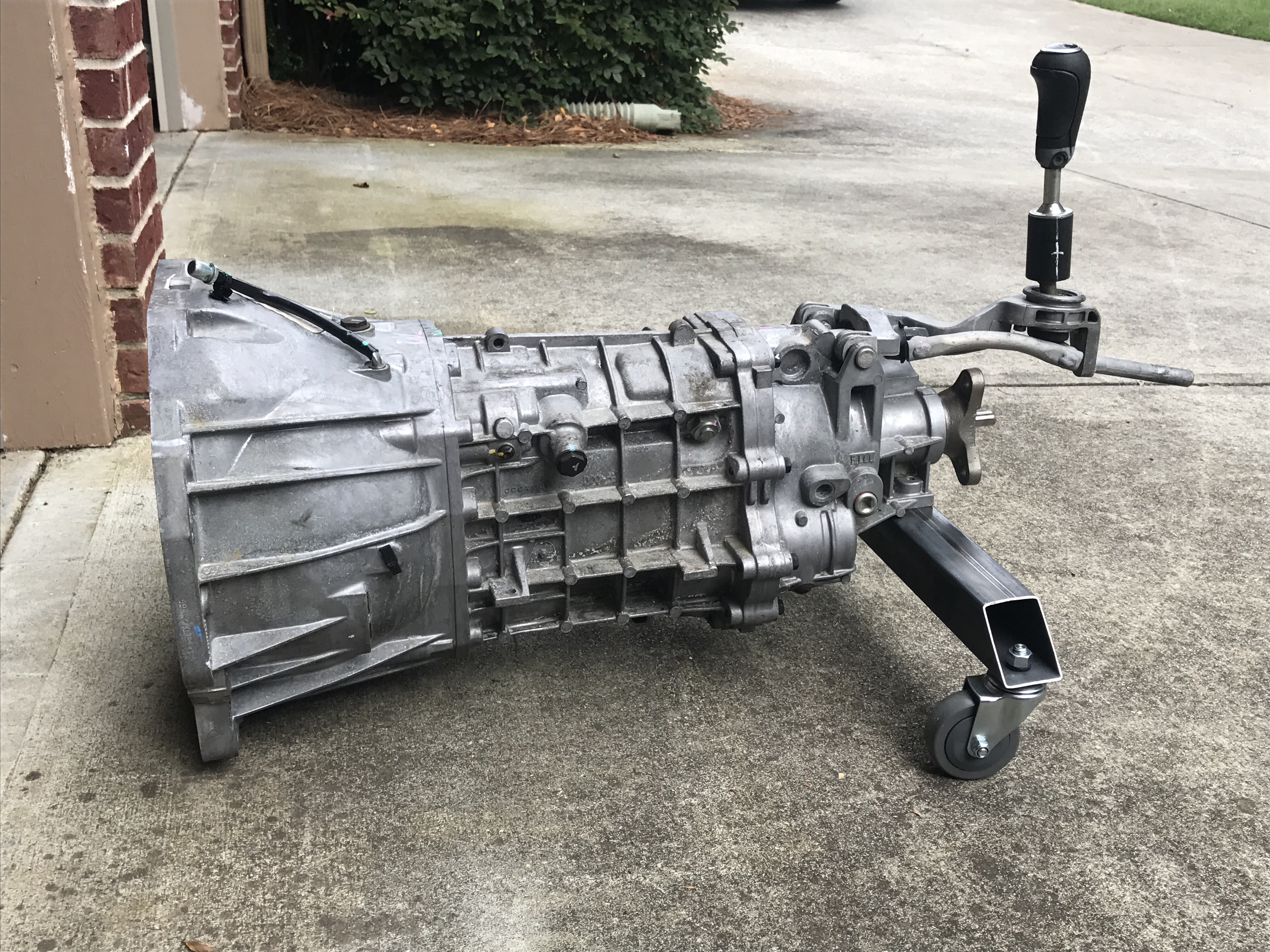
Anyone want a miata engine? I have a deal 🙂  94 Miata with about 80k on it.

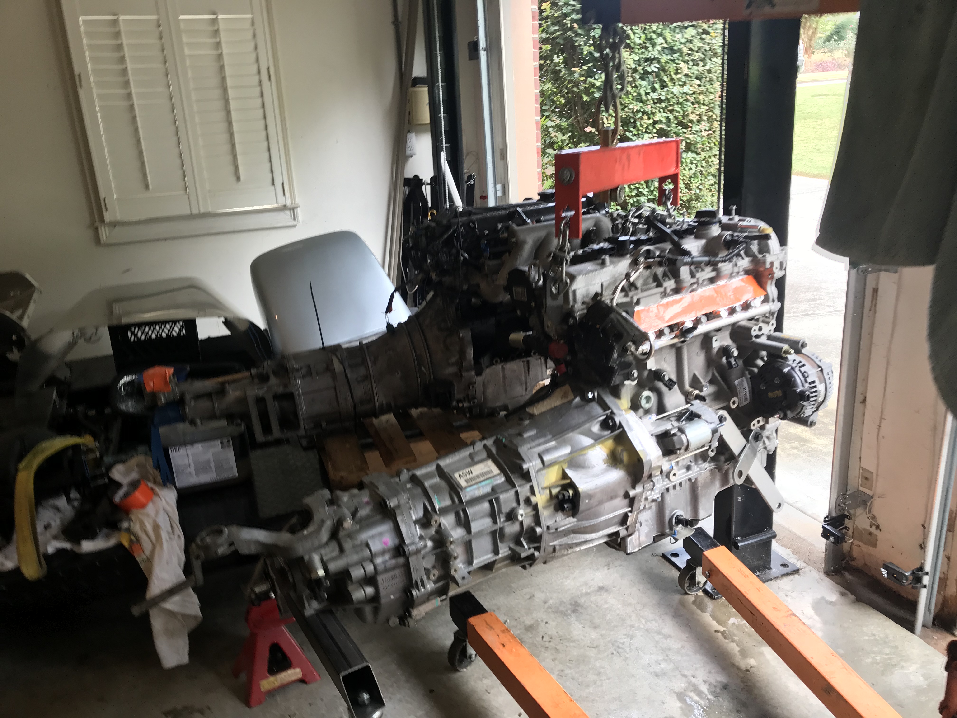
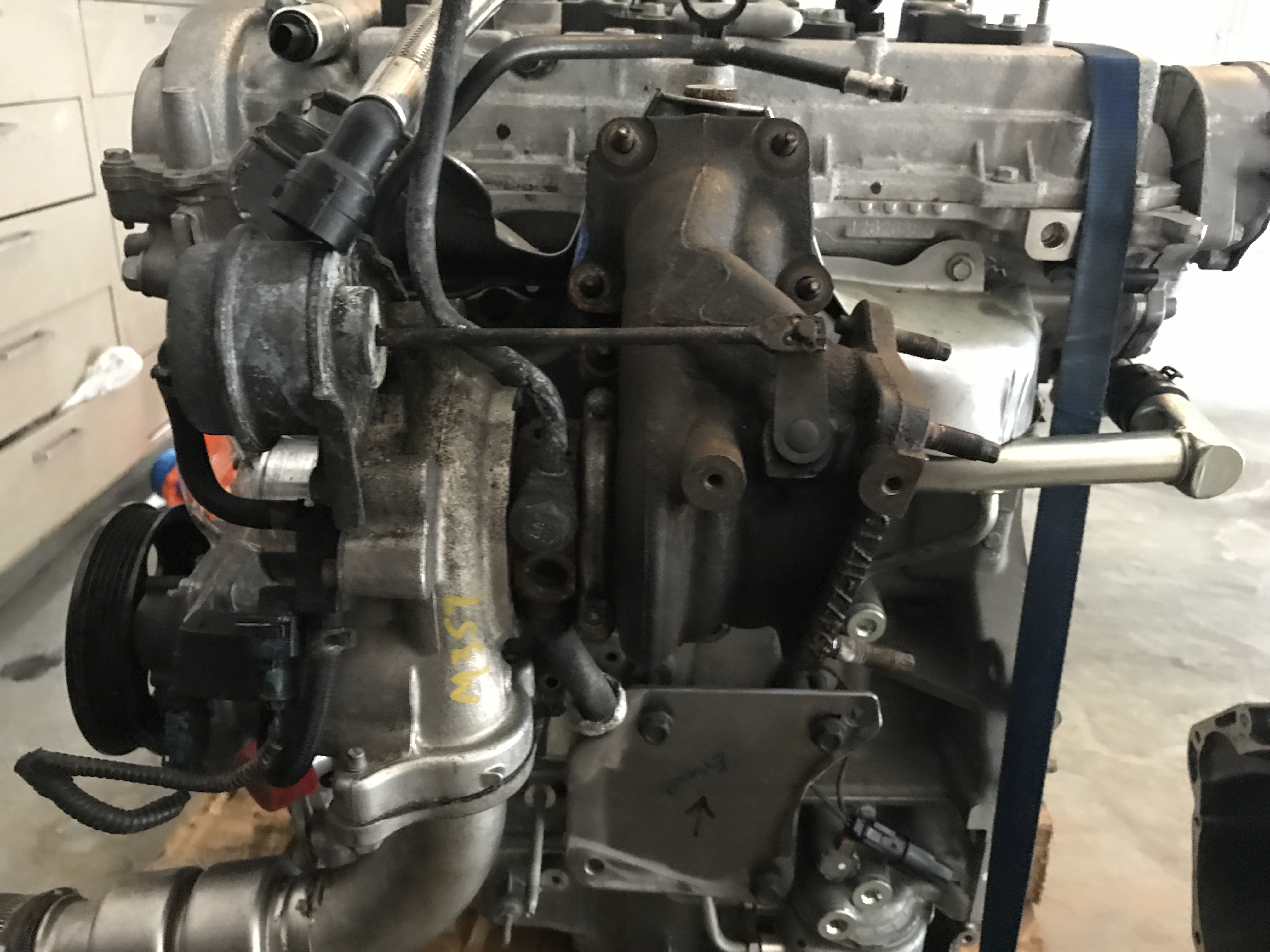
Side by side View. Ecotec in the front.

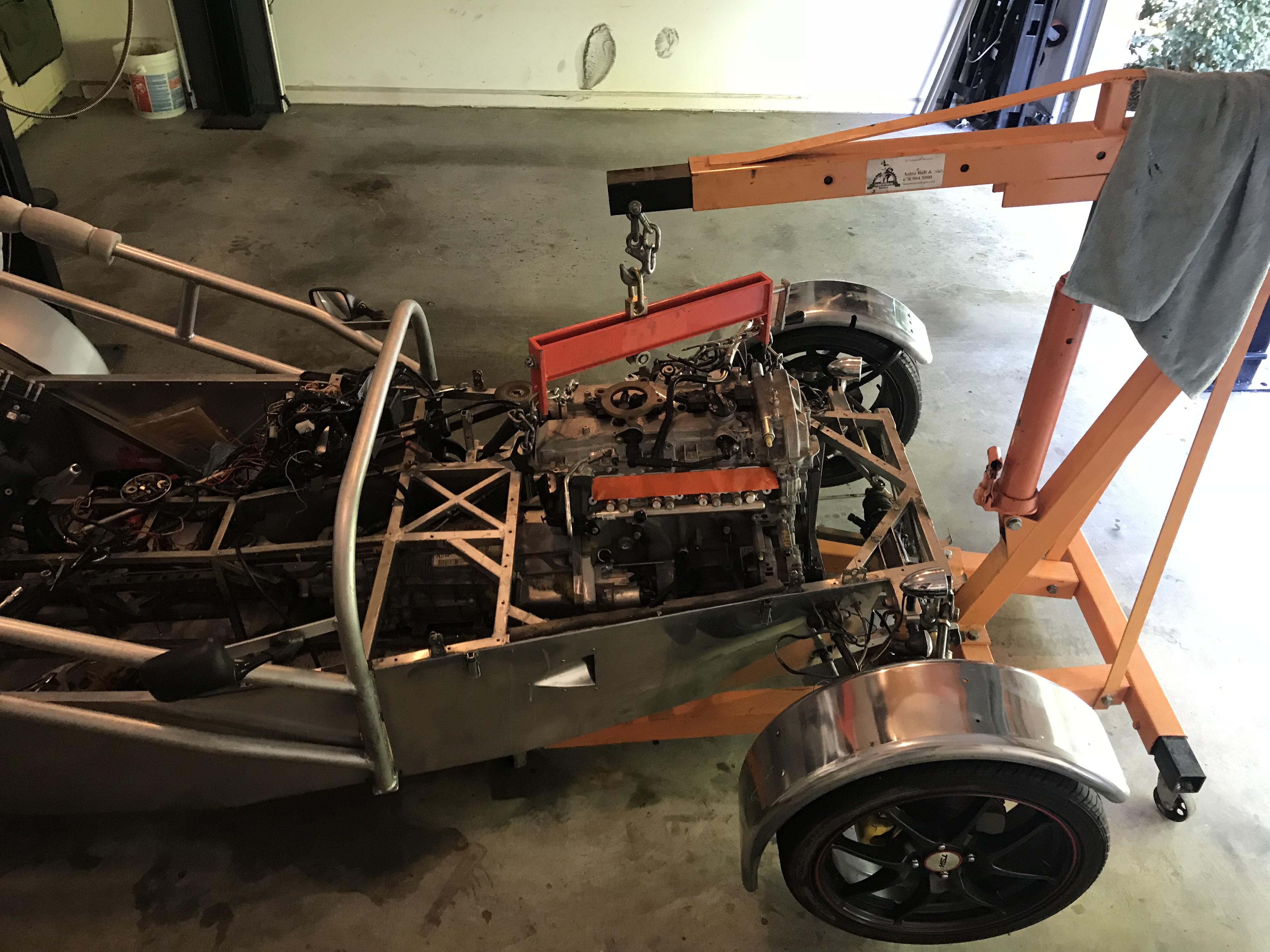
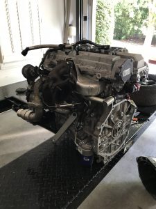
New engine in.. Kinda! I had to cut out some trans tunnel bars. The engine is a bit wider and taller. Taller was expected. Wider not as much. There will need to be some modifications made to get this to work.. The fight isnt over!

Here is a video of the walk around

I now pronounce you engine and transmission…

What started and has been a major headache is behind me. I landed up buying factory bolts and intended to have Fidanza drill the holes bigger.


Soon after I received them I thought it might be easier to cut the bolt heads down in the lathe. Thanks to Cawley racing we were able to shrink them down and re blue them. Success!

After the install I started on the clutch and pressure plate. With a clutch alignment tool we were quickly in business again.

Up next I man handled the transmission on to the engine and bolted things together. Even the starter motor aligned so it was a good day

Up Next is the engine wiring. All parts are sent to the harness maker and hopefully I’ll have good news soon and be ready to drop this into the chassis!

The Fidanza Fiasco continues…

What started as a promising morning didn’t end very well. I pulled the motor mounts off of the engine and welded on the needed offset pieces. Things were going very well! (note the metal braces going forward is to prevent the engine from rocking)

Using the”custom bolts” needed for the flywheel I managed to get all 8 in place and hand tight. I’ll admit I don’t love that there is no locating pin on the flywheel because it allows all of the rotational torque to be transmitted through the bolts to the transmission.

This is what the bolt looks like. It’s an m11 -which isn’t something you can easily find and definitely not something Chevrolet dealers usually stock.


After hand tightening the bolts I grabbed the torque wrench and set to 20ft lbs I wanted to get everything started and check alignment.

The first bolt achieved 20lb fts but the next 2 appeared to strip out. At this point I stopped and removed all 8 bolts and inspected the damage.

Even though the bolts appear hardened they lost their threads quite easily. The crank was inspected and it is fine.

While not ideal I’ll give a few vendors a call on Monday and try sort it out. Unfortunately m11 is a very uncommon size so this won’t be easy

Finishing up the front of the engine

To finish the front of the motor I needed to find a way to tension the belt due to the fact I wont have an AC compressor.

To start I went to NAPA to get an Idler and a belt. I wanted to mount the tensioner high up since my engine often sits below the frame rail.

Pulley came from NAPA. It is grooved and part number 409703

This wasn’t the first belt I bought. I think the factory part was 1940mm. I went to 1740mm to get a good fit.

Napa Part number 050685- It is a 5 Rib 1740mm belt.

This shows the belt route and the rough placement I was considering. Note my tensioner is smaller than the factory AC Pulley.

Bracket created using the 2 front bolt holes. It is a solid fit so I didnt feel like I needed to move further back and triangulate.  Note the location is higher than an AC.

This is the side view. It was essentially 2 pieces at right angles with a brace to stop deflection.

This is a close up view of the bracket. I painted it while hot so the paint bubbled. I like the look.

The end result is fairly good. I am happy and things appear to be tracking well and cleanly. I might add a nut to the back of the bolt. Right now I have tapped the steel plate (3/8″ thick) so I think it is good enough.

Clutch Parts needed to make a braided Line

If you own a Camaro or ATS chances are you have the same transmission I am using.  The one piece I will be using is the stock throw out bearing.  Unfortunately The clutch hose I received was cut and my car actually has a steel braided AN line today. I plan to simply unscrew the -4 fitting that attaches to the miata slave cylinder and thread this piece on. That should be all that is needed to operate the hydraulic clutch for the LTG.

Part Number 139160 from Summit Racing

Turbocharger Arrived

Turbocharger Arrived this week and I quickly mounted it in a mock up fashion.  Finding the size nuts and bolts for it is proving it be a royal pain in the ass.

It is a used unit from a junk yard off a stock motor which should be good enough for mock ups and to get things rolling.  The air exit pipe actually fits in a good spot. Hopefully it will stay within the body lines.


Missing the factory heat shield but  can make one fairly easily.  If anyone knows the nut size or part number for the turbo please let me know. 

The turbo came with 1 oil pipe but  the other is missing and will need to be bought.

The turbo mounts further out then I would like but hopefully it will work.

Water lines need to be made/purchased. Unfortunately without using the stock radiator and coolant tank it may be another custom effort

Engine Preparation

This weekend I started cleaning the engine (Brake clean is the $hit!) with the intention of mounting the flywheel and trans in the near future.  There are some cheap engine stands on amazon for $40 but I don’t feel they would bolt up easily. I will probably start to build and frame up something that will offset the engine and make transmission attachment plausible.


For the transmission I added a bar at the back with 2 casters. That makes it easy to pick up the one side of the engine and slide it around.

Car is in the background. I do feel the intake manifold will need to be replaced with something custom to prevent the large side bulge.

I could use some help. If someone knows the connector that I could replace the clutch line with I would appreciate it.  The factory line was cut and this was the connector that is left (It goes into the clutch slave cylinder). Ideally I want this piece to a -4an fitting to connect to my Wilwood master cylinder.

Ordering some parts for the LTG

I recently bought clutch cover bolts online and ironically 6 packages came from a GM online dealer.  To my disappointment each only had 1 m6 bolt within it.

This is the GM throttle pedal. It isn’t ideal because of the angle that it mounts but some fabrication can make it work. Because the ecu is drive by wire a new pedal was needed.  Here are a few pictures showing the pedal

LTG Motor Mounts

To get the motor off of the pallet I wanted to build a “skate” to hold the engine and trans. My goal is to add wheels to the engine and the trans and have an assembly  that can move around and probably running.

This is the passenger side of the engine that a mount needs to connect towards

 This is the drivers side of the engine. 
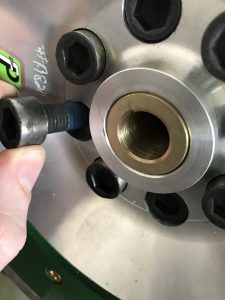
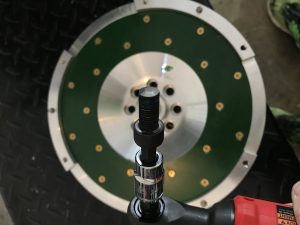
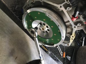
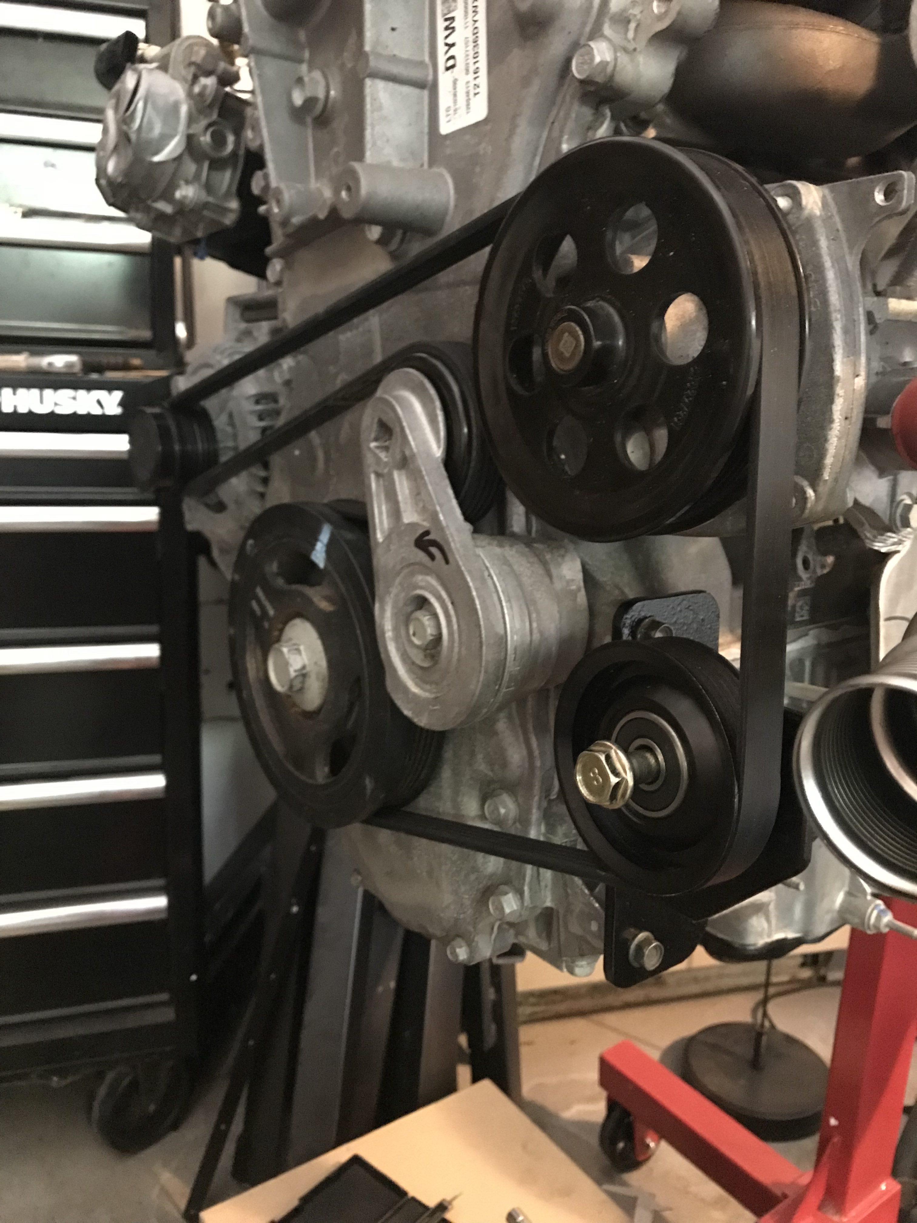
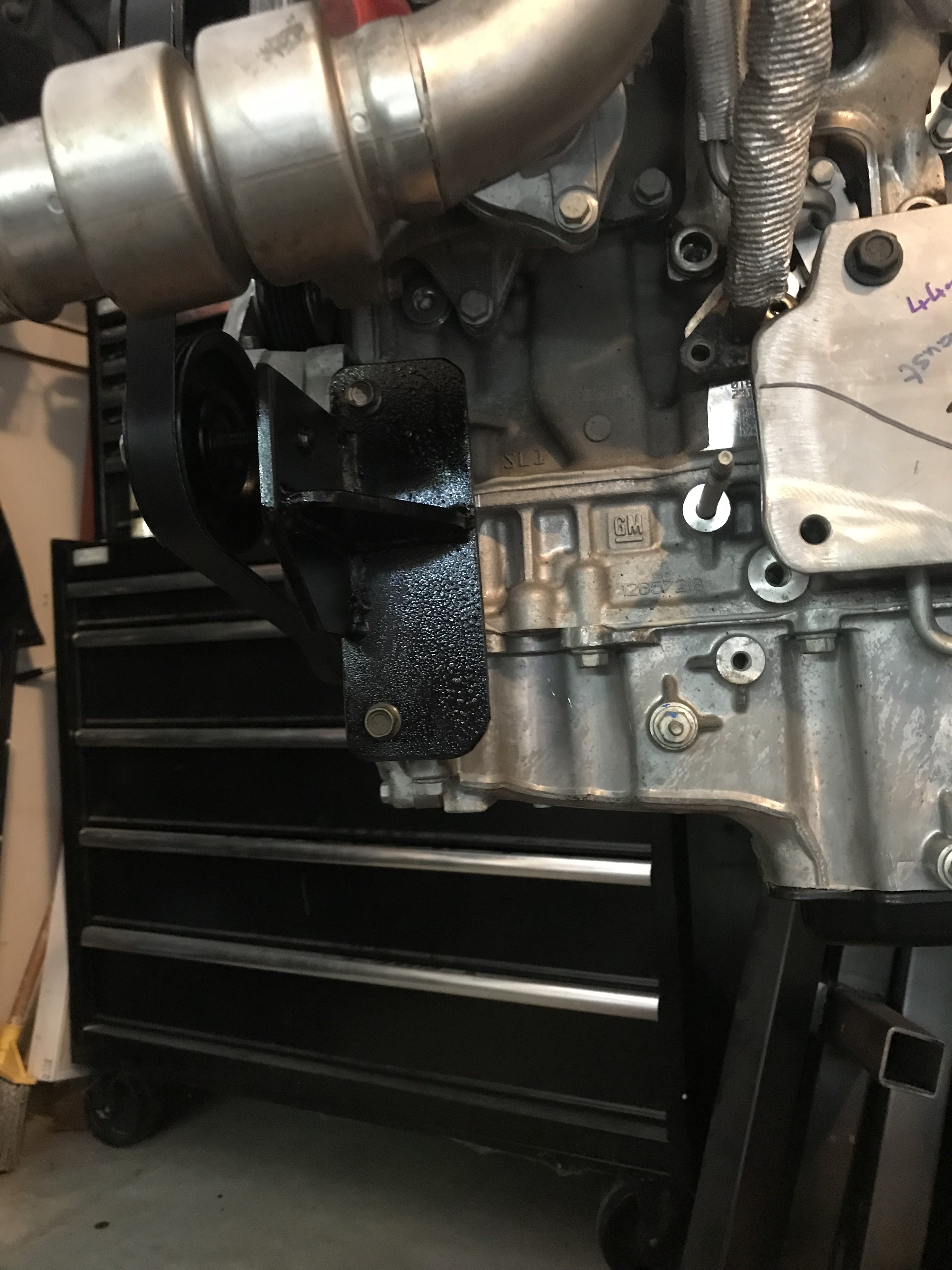
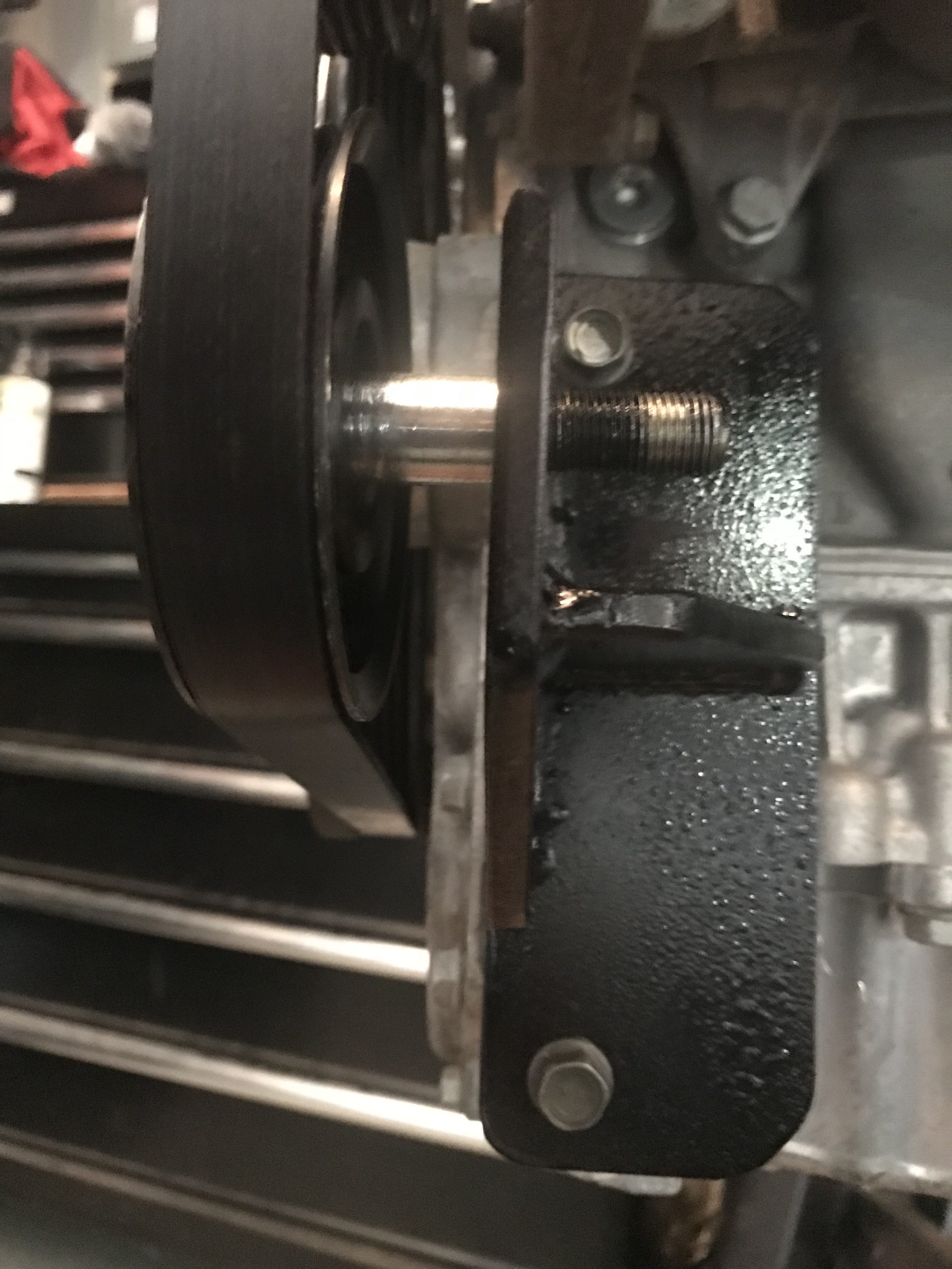
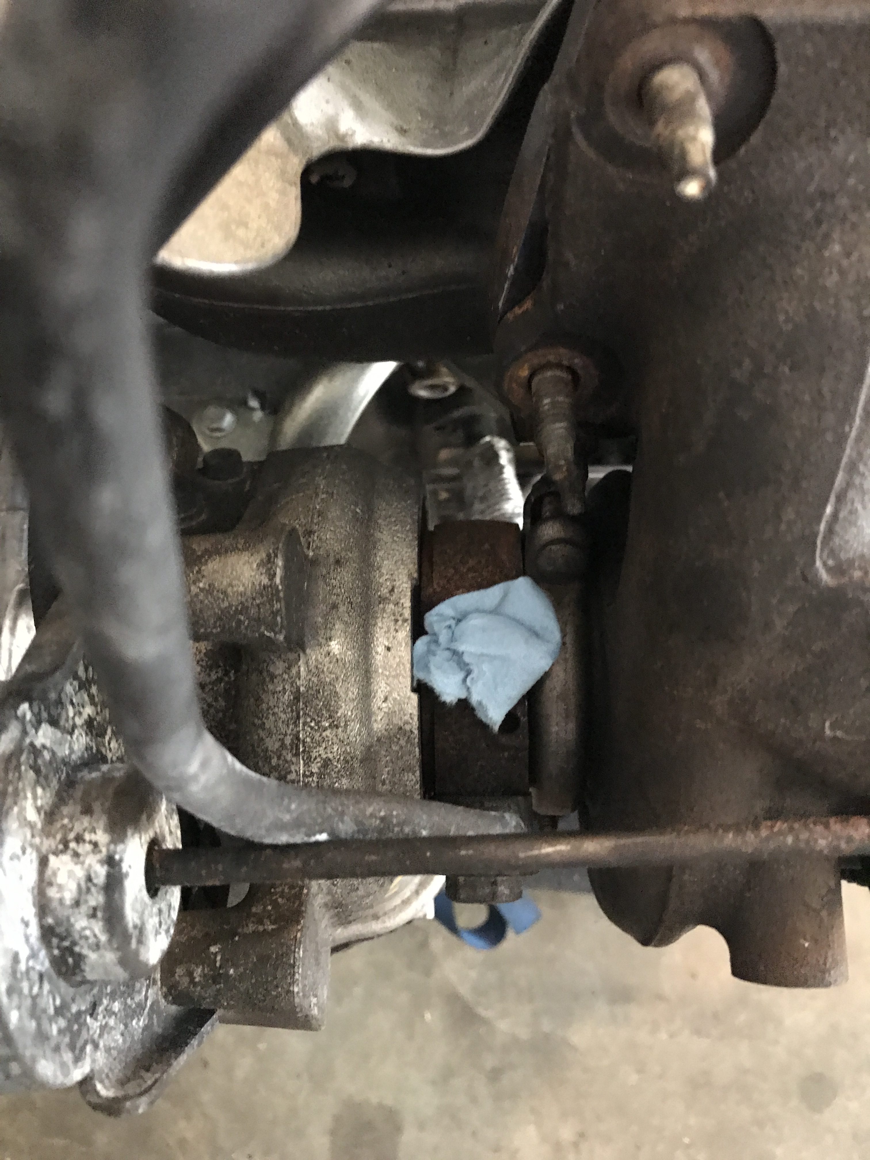
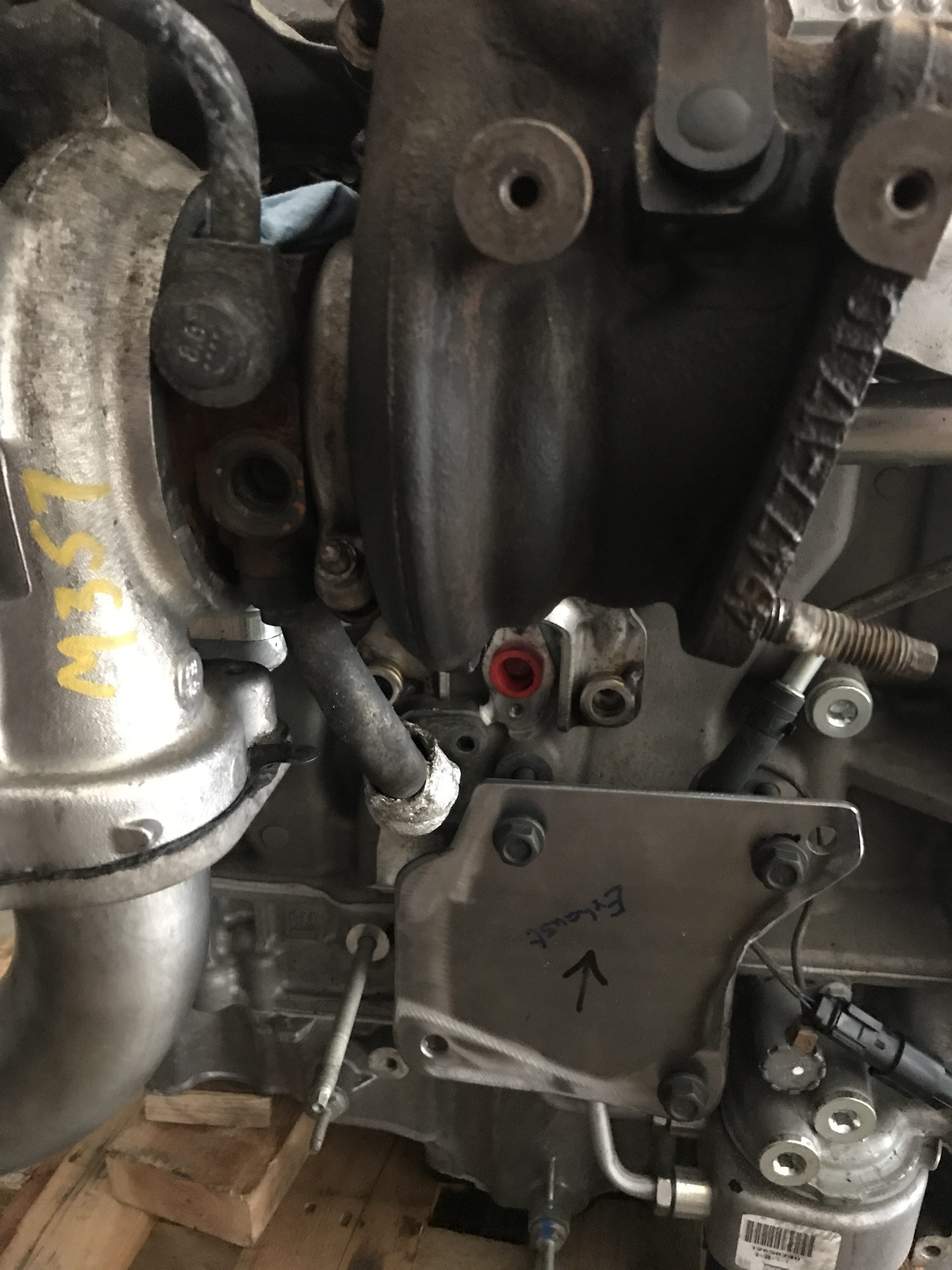
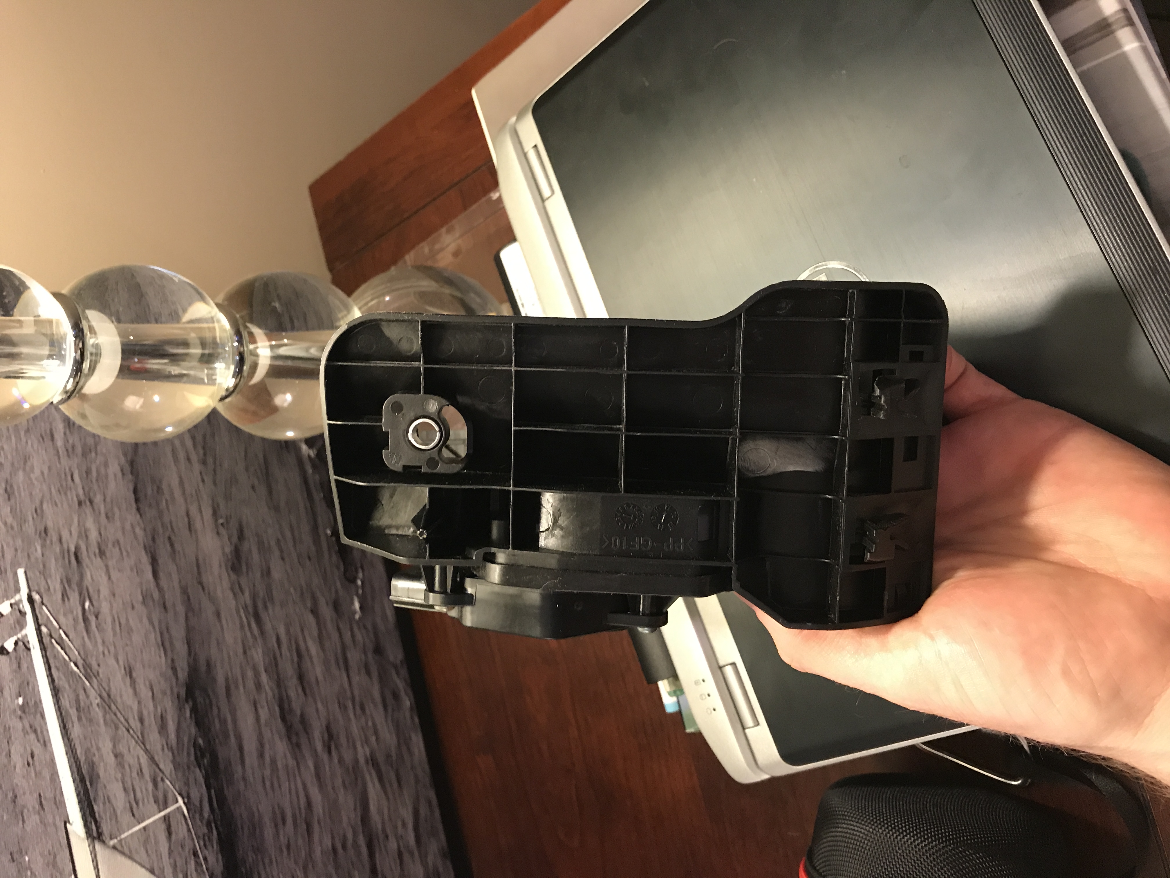
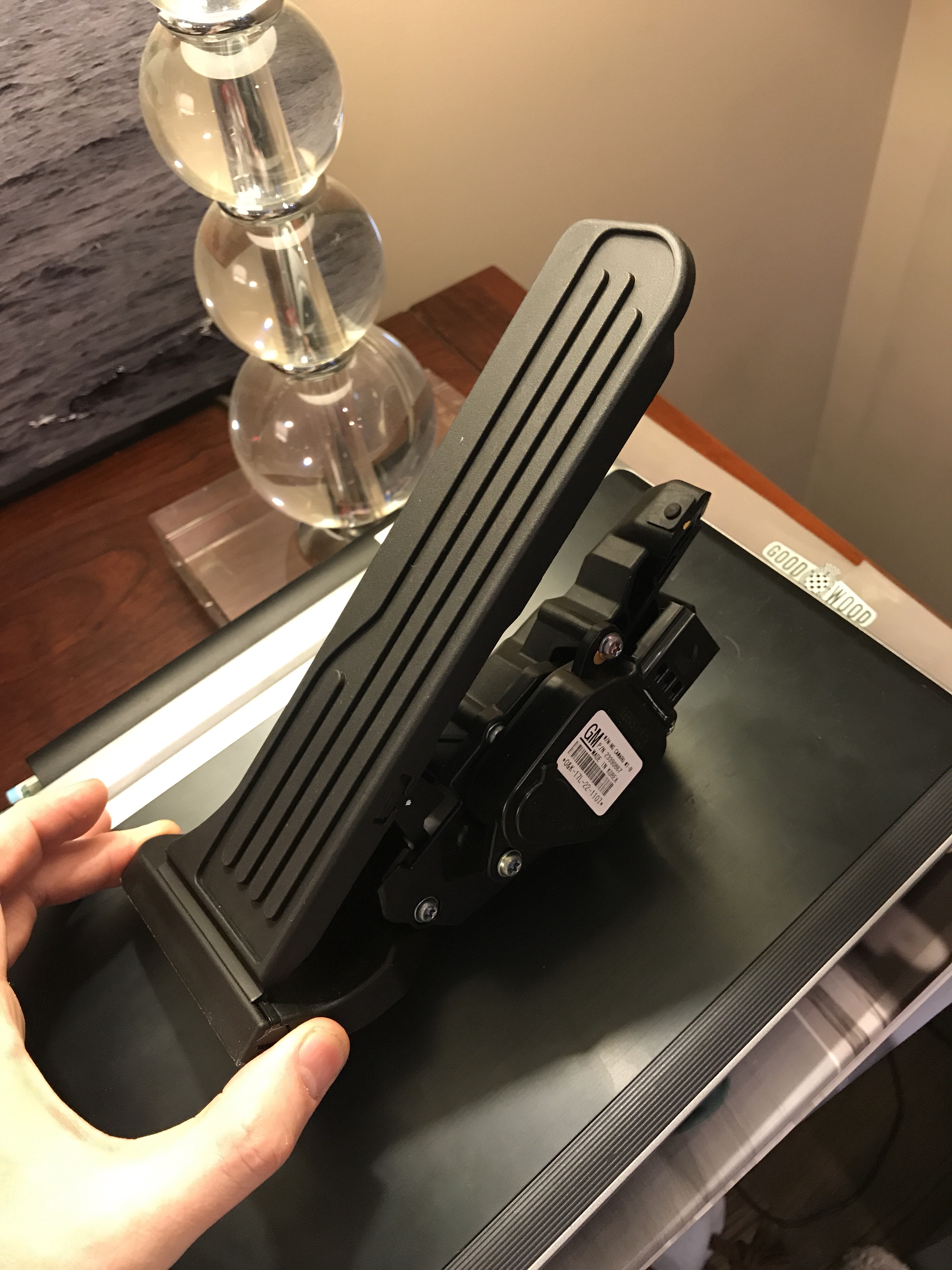
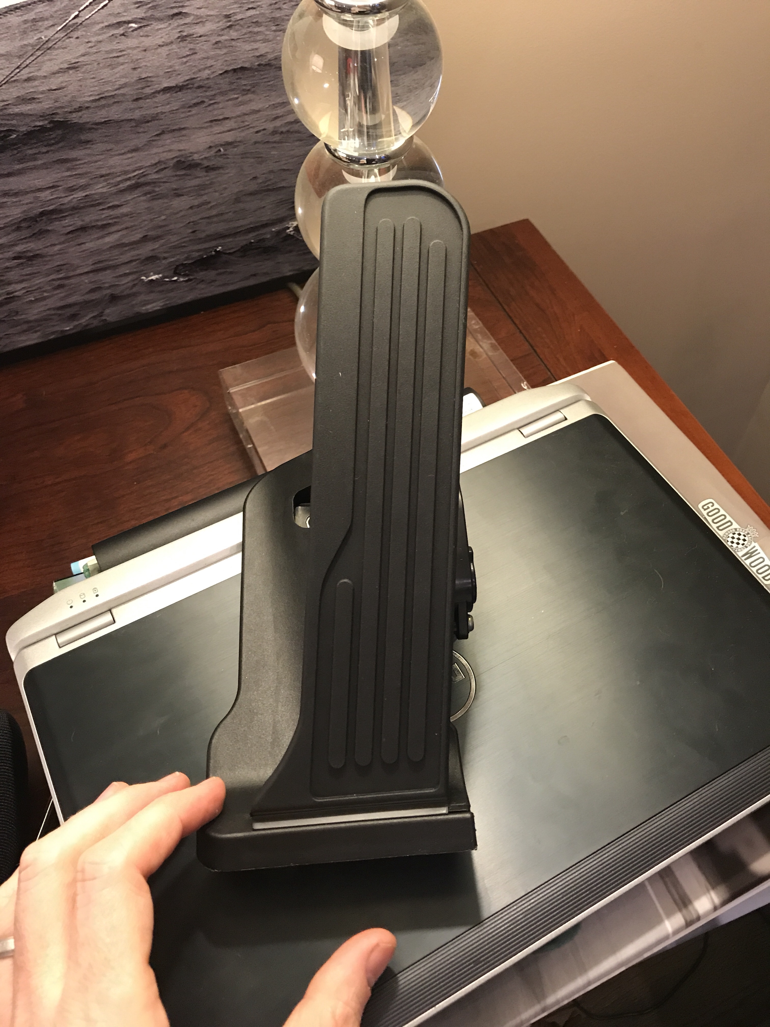
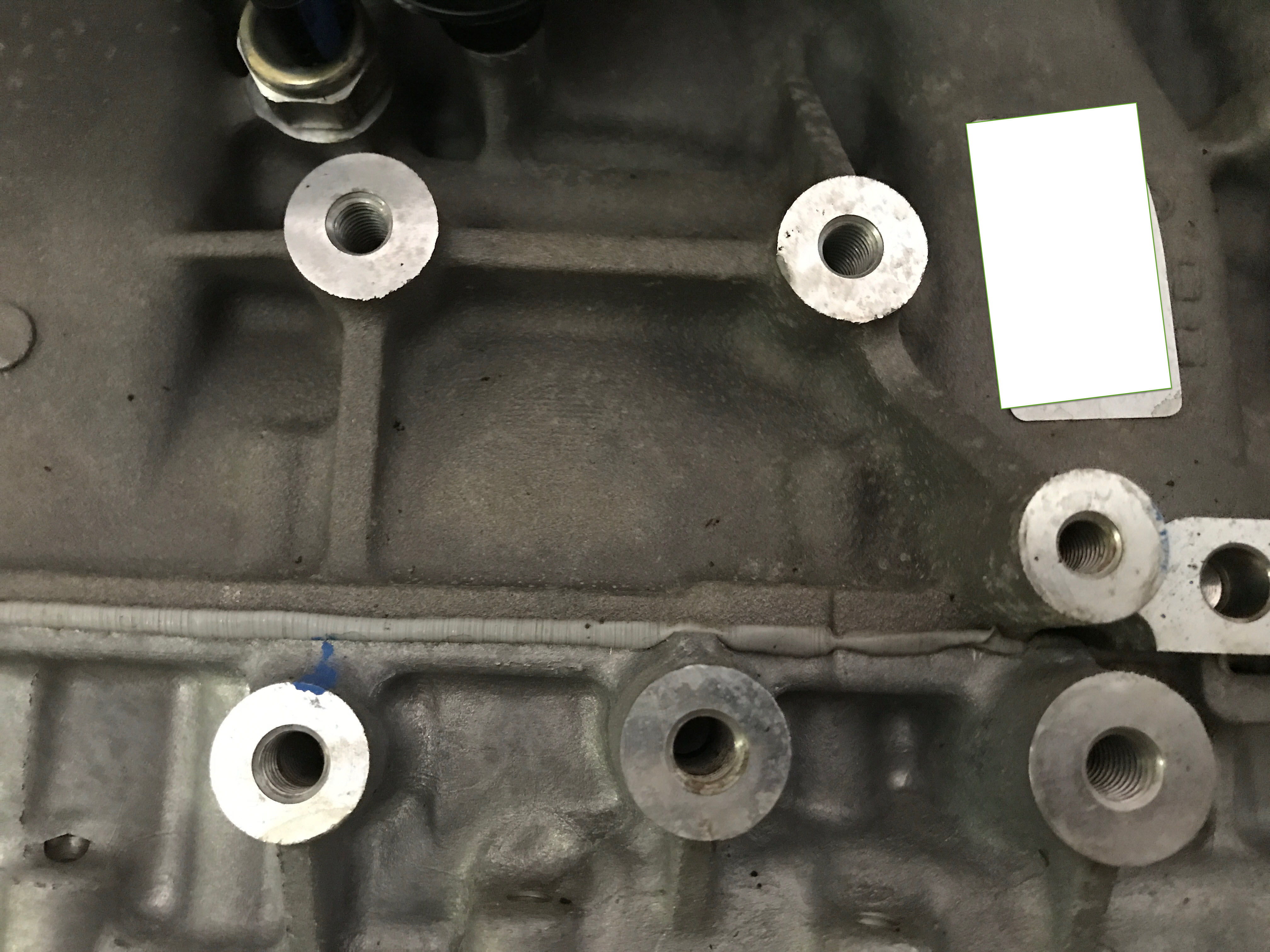
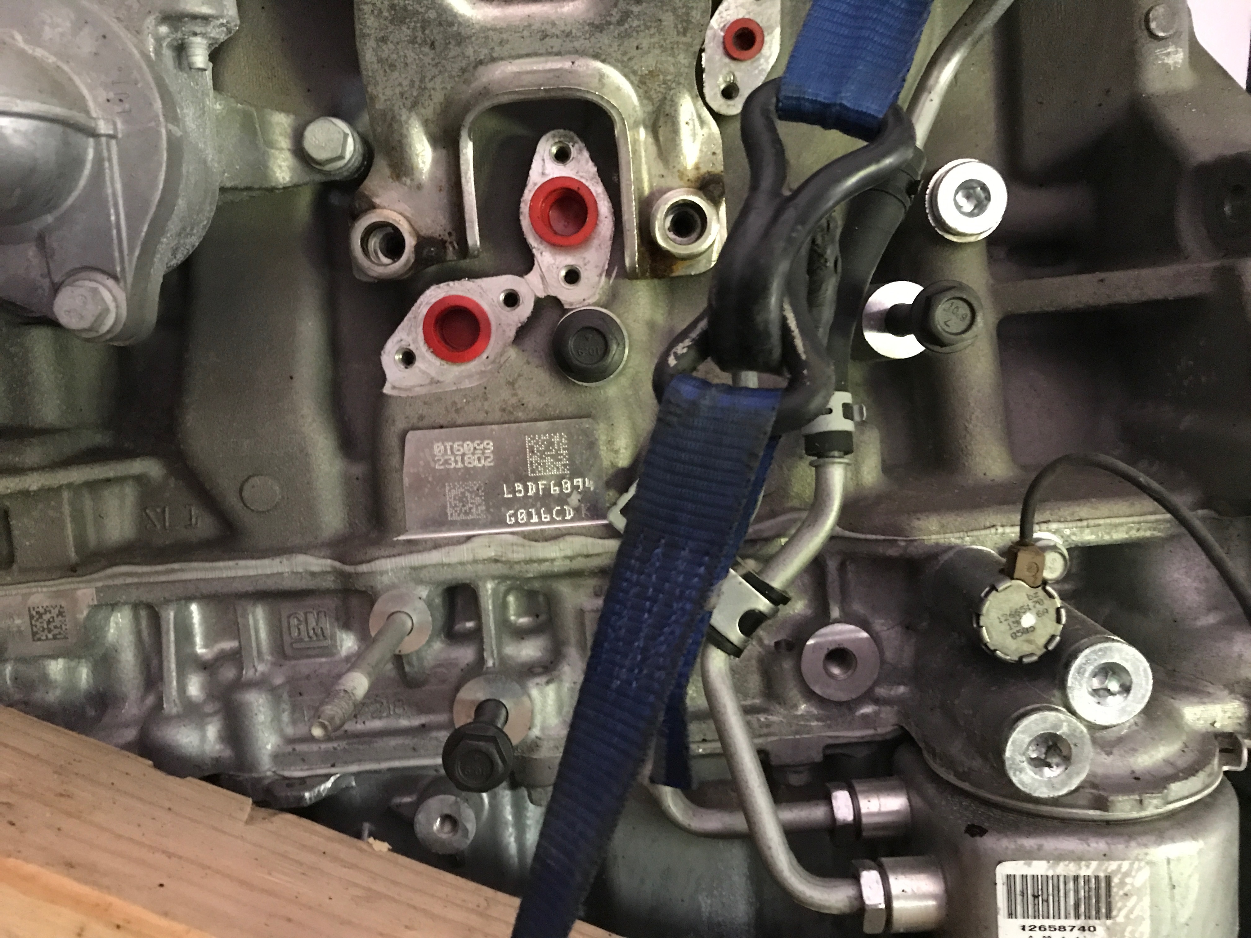
This is what I suspect the mounting plates will look like. 
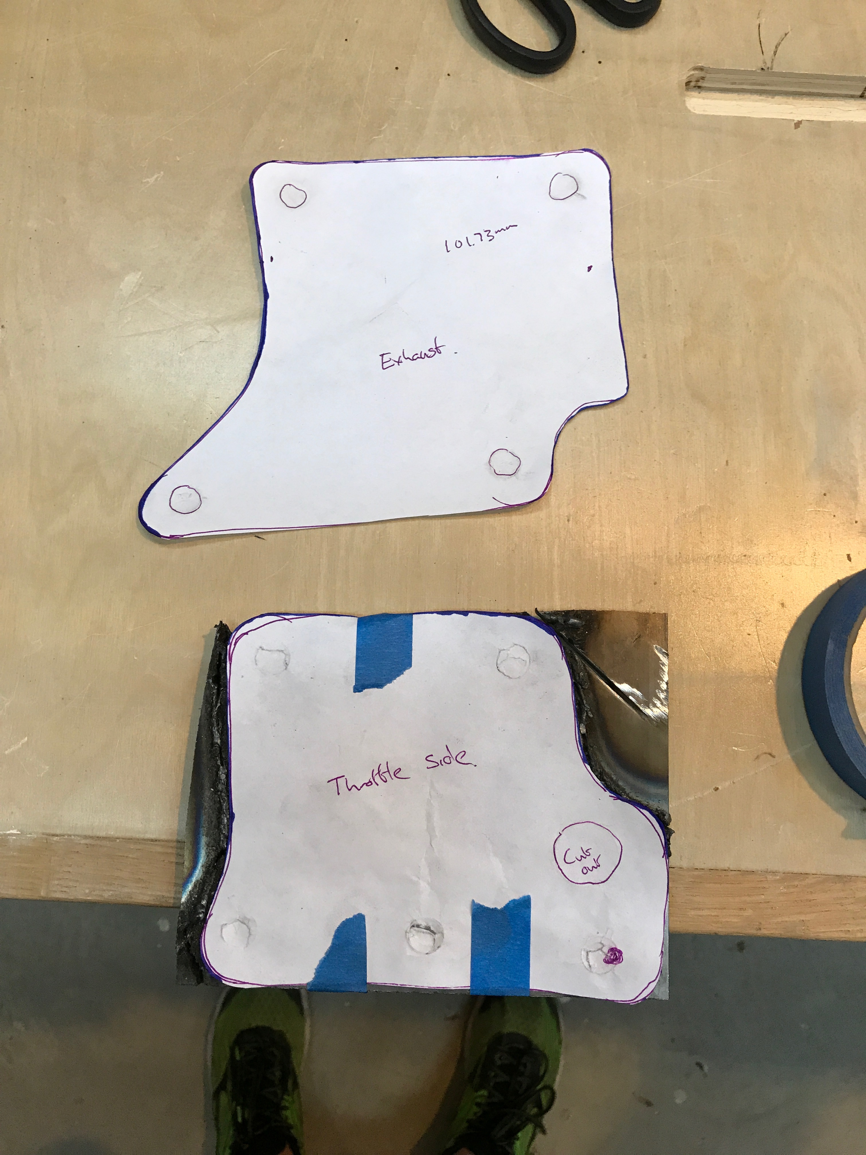
I tried to mount the paper version on a piece of steel and trace it out. My goal was then to cut it out with the plasma cutter. Unfortunately 25 amps was not enough and the breaker would trip at that point.  A 4.5″ angle grinder did a good job and soon after I bought a bunch of flap disks with the intent of getting them to being really smooth and pretty. Next up I need to measure and cut spacers as the plates will not bolt flush to the engine block.

More to come..