Almost done..

Finally got to one of the finish lines… After many pieces coming together we made some big progress.

First was the valve cover. I did not need to replace the black unit I had before but I did need to weld to -10AN bungs on the cover for routing to the catch can. I went with white because it is the easiest to see dirt/oil etc. The 2 ports route forward and empty into a tank at the front.

Body work was rather simple. I was able to get keep the sides open to vent out a lot of heat.

Long term I would probably place several pieces here to allow air to exit better. It is nice to be able to get to the jacking port so easily.

Everything under hood looks good and tucks nicely. The turbo guard is hopefully up to the job. If not we will have to get creative.

With the hood on- You can see the turbo but generally it looks fairly clean and sleek.

Intercooling!

Originally I thought the intercooler would be a quick and cheap project I could simply throw money at.. I was wrong. The sizes I could find were either too small or too large. The issue of exits being incorrectly placed was not a major issue.. So what was?

I wanted the intercooler to be placed in front of the radiator but also not block any more surface area with end tanks than needed. The solution? I turned to CAD- Cardboard aided design! I used the dimensions of a Garrett intercooler core and worked out how big I could make the end tanks to fit.

The CAD model was perfect and I was able to remove the pieces and lay them out in some 1.8″ 5052 Alumunium. After some cutting and tacking we had a pretty great looking intercooler! I fired up the Primeweld 225 and went to town. Things were going very well!

Until the pressure test… After several attempts to find the leak I kept on chasing an area between the core and the end tank. I would grind it down and reweld it a few times. Eventually I got frustrated and took it to a radiator repair place and they verified what I couldn’t believe- the core was leaking but in an area that would require the end tanks cut off and welded. After talking to the company I bought the core from they told me that Garrett was not being helpful and “they were truly sorry.” I won’t buy anything from Garrett again and had to cut off the tank, fix the core and then weld it again. Visually it doesn’t look as good as it did originally and I am going to hold a grudge on this one!

The end result should work well. The end tanks do not block the radiator and it appears to work well. One more project in the books!

Intake Manifold Adventures

After lots of fighting with the intake manifold I decided to stop being cheap and throw money at the problem. What was the problem you say ?

Pardon the dirty alternator..

So the Skunk 2 intake manifold was never designed to be flipped for a RWD configuration. It has the modular design but the flipping is better suited to a K24 than a K20 because of the shorter deck height by 1″.

The intake manifold was a disaster from day 1! It requires that you cut the water pump housing to make it fit and then use spacers/washers to tension the alternator. After hacking up the housing I found that I was still likely to hit the alternator. The solution? I tried to buy the spacer that makes a B series throttle body work on the K series intake. I never attempted to install it and landed up selling it and the intake and ordering the Kmiata intake manifold and throttle body. It was backordered but worth the wait. I did follow the recommended guidance and bought the misalignment spacers due to the flanges not being parallel.

The manifold had the water passage built in which was a nice change and something I didn’t need to buy another part. Generally the fitment is good, the IAC did need a new part (from ebay) but that fitted nicely. All in all it was something I should have done from the beginning.

K20 Power now bolted in!

It took a while but I snuck a half day into working on the car with my dad. While I thought it was 3 hours of work it actually took 6.

First thing was to pull the k20a3 and remove the transmission and adapter plate.

Up next was moving those parts to the K20z3 and bolting them all back together.

From there we worked out what needed to be changed and we we removed and replaced a tube in the chassis. We also removed the old motor mounting plate and cut a new piece. After 5-10 minutes of welding we started to position the engine.

After measuring and cutting several tubes we had the left side mounted. Next we leveled the engine to 0.6 degrees and started on the driver side. They came out quite well

The final step was to check hood clearance. I didn’t expect it to fit but was nicely surprised. 3 mm to spare!

There week be some challenges with the steering and alternator but those are for a different day!

Ground clearance is a nice and acceptable 4″

Up next is the transmission mounts!

Let’s try a Honda Engine!

In an interesting twist it looks like we may be considering a Honda engine. After looking for small footprint and low heat options the Honda K series engines came to the top. After reading about using it with an S2000 transmission it appeared to have legs.

Hours of research highlighted that the S2000 transmission wasn’t a great choice for big power I somehow landed on a website- kmiata.com. These guys make adapter plates that allow the Honda motor to bolt to a Miata transmission. If I had not sold mine previously I might have had the swap up and running a while ago.

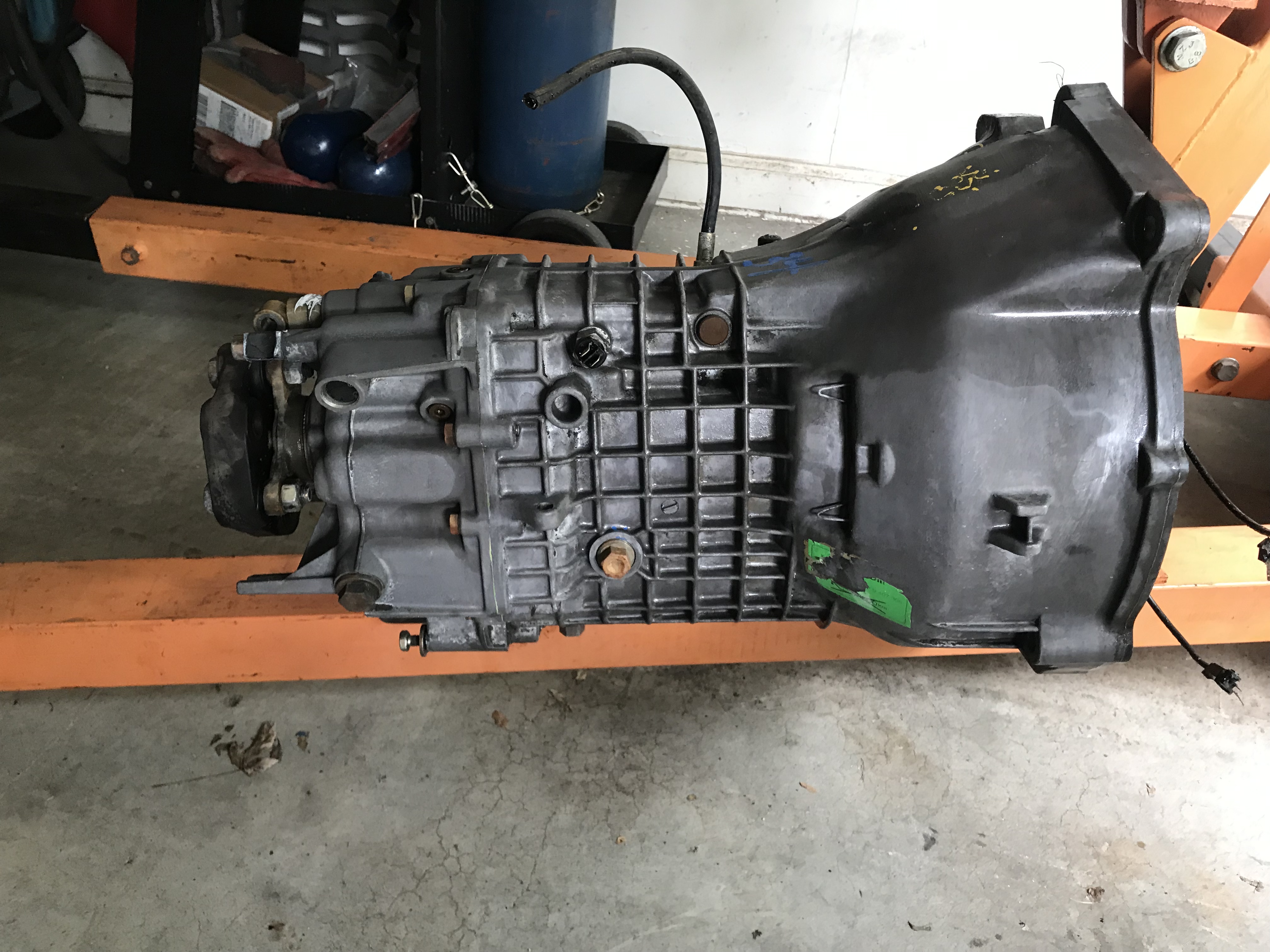
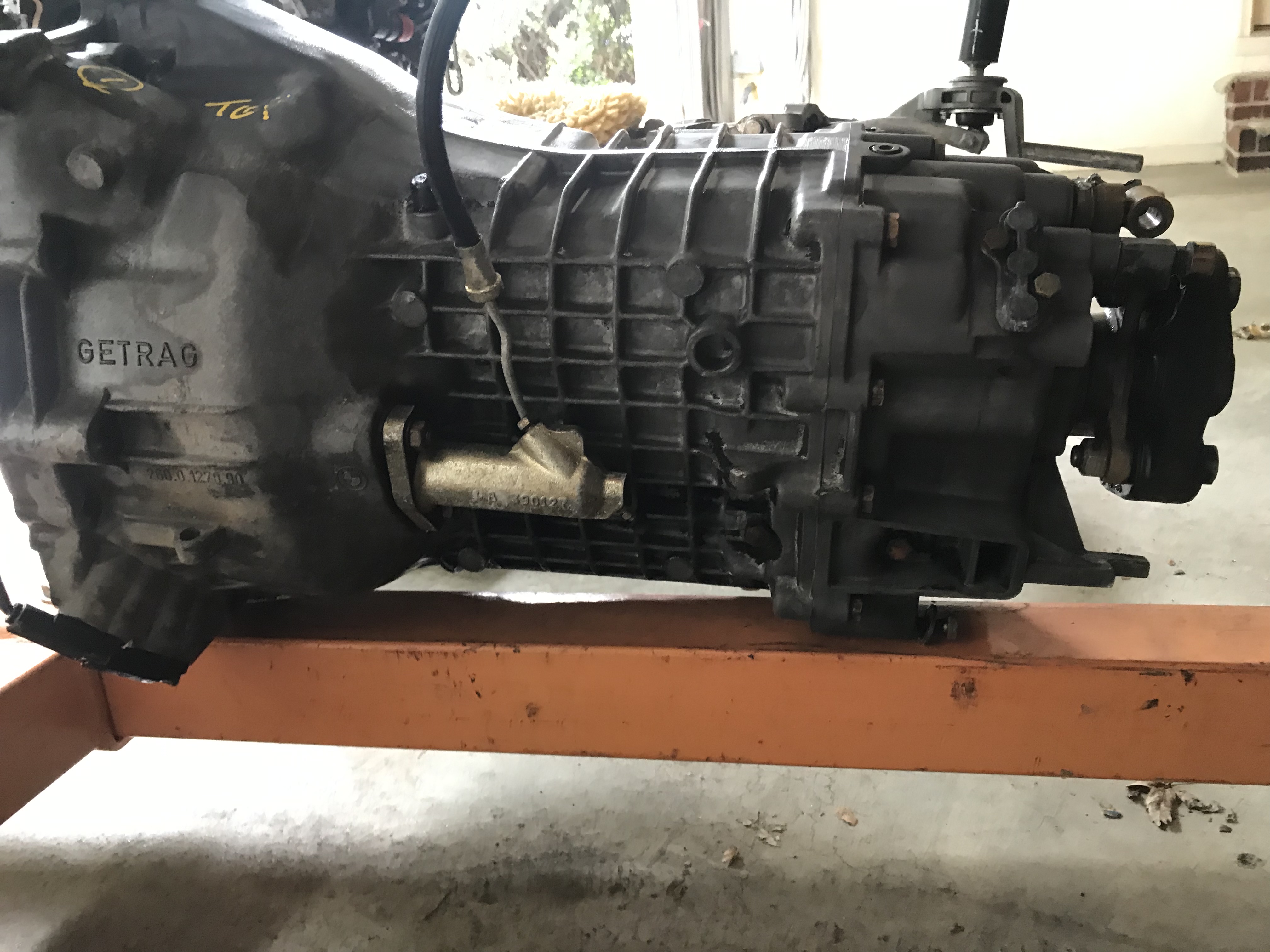
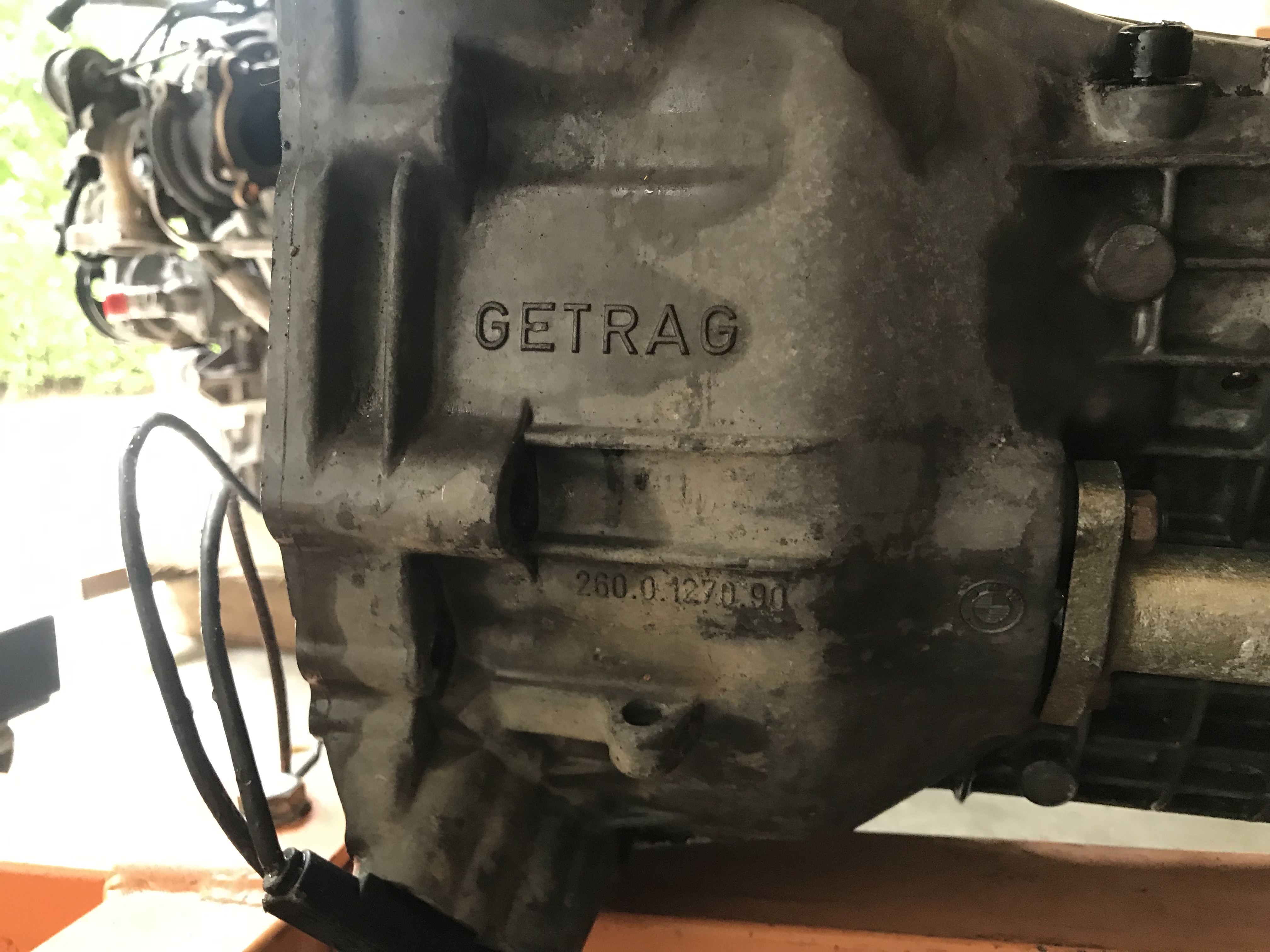
Given the option of a BMW Getrag 260 gearbox I decided to try find one. That was no way task! Luckily eBay helped and I found one about 20 miles away. After a good cleaning it looks pretty good! It will be a while before we understand its condition but it appears to have 5 forward gears and 1 reverse.

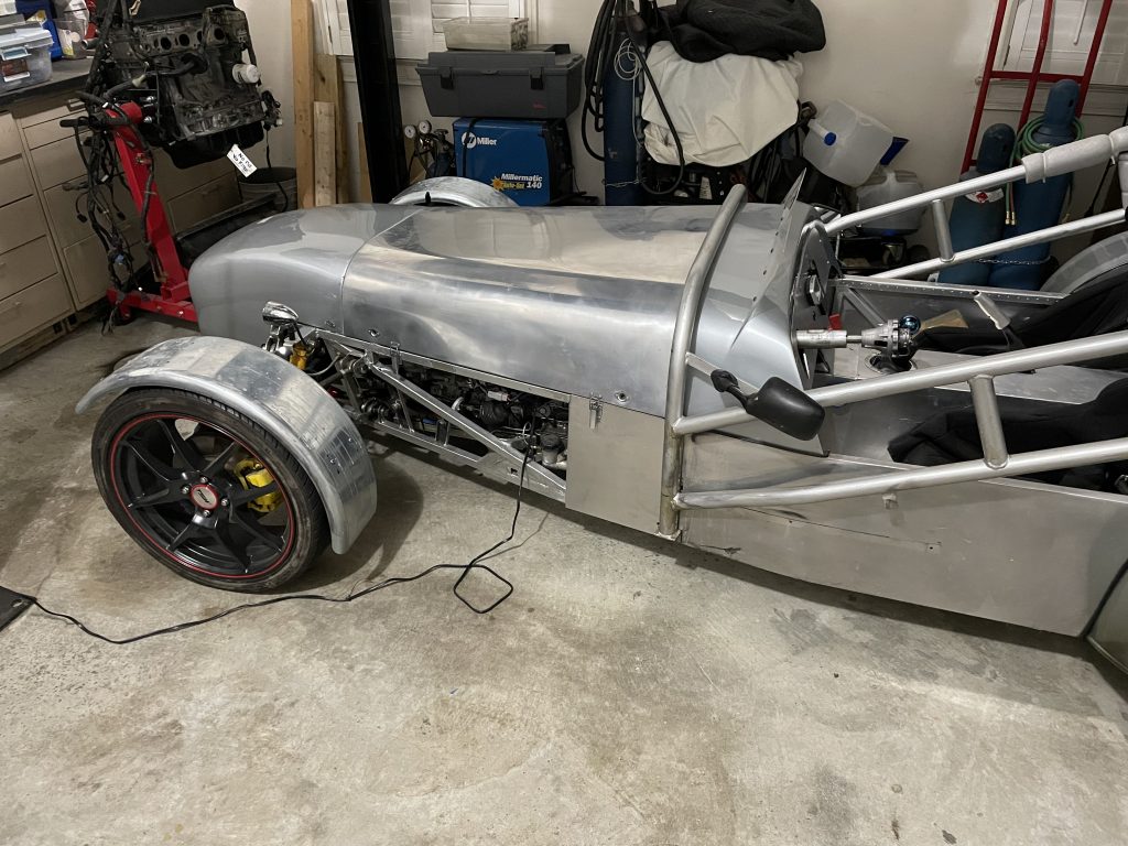
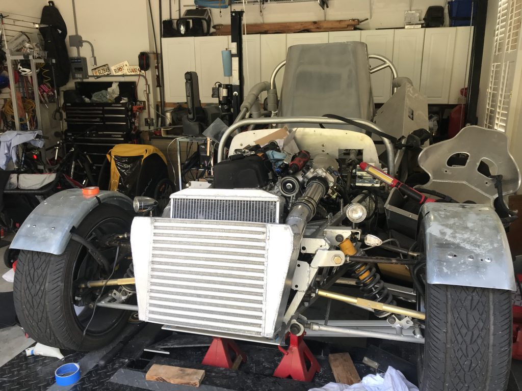
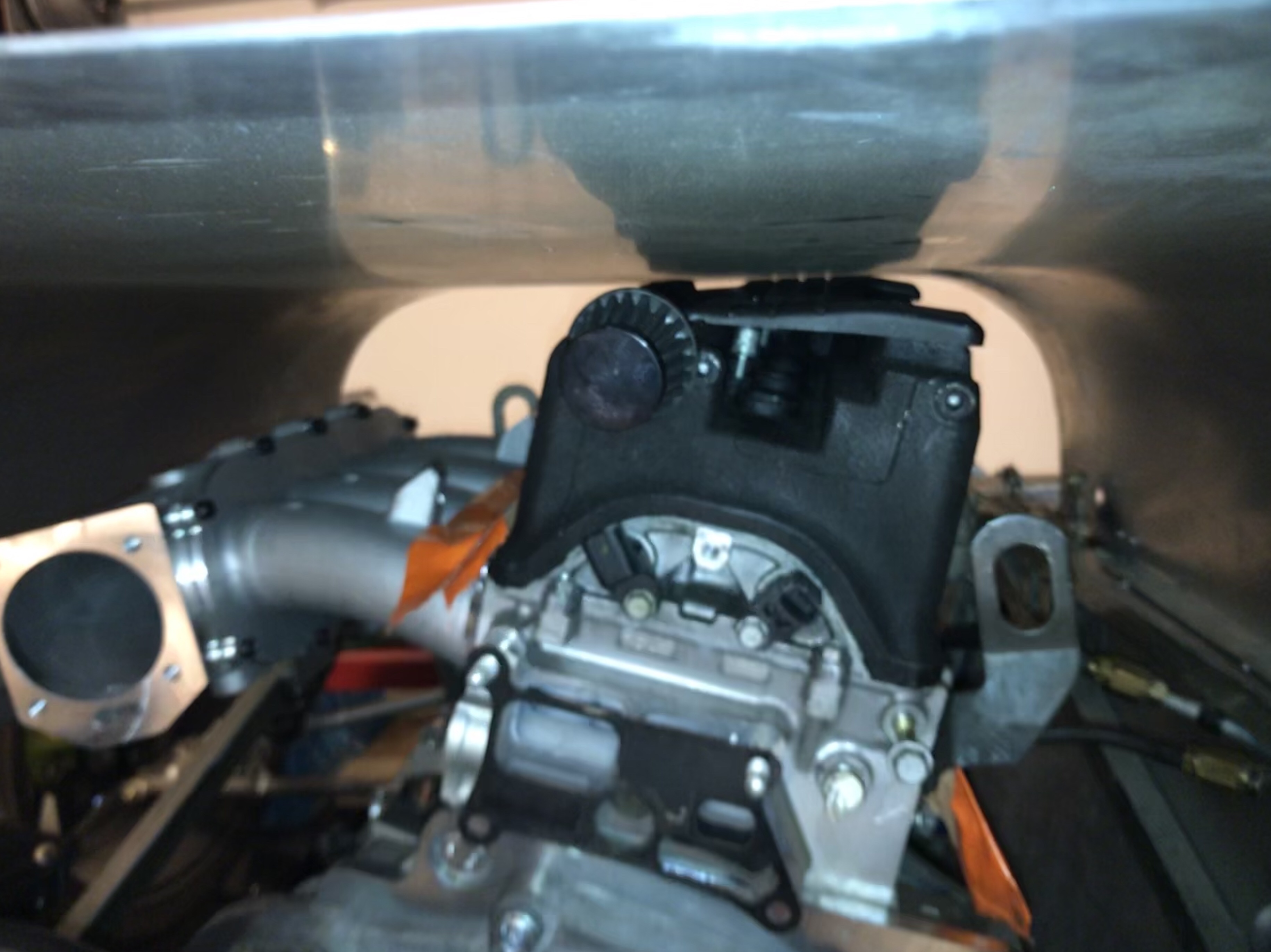
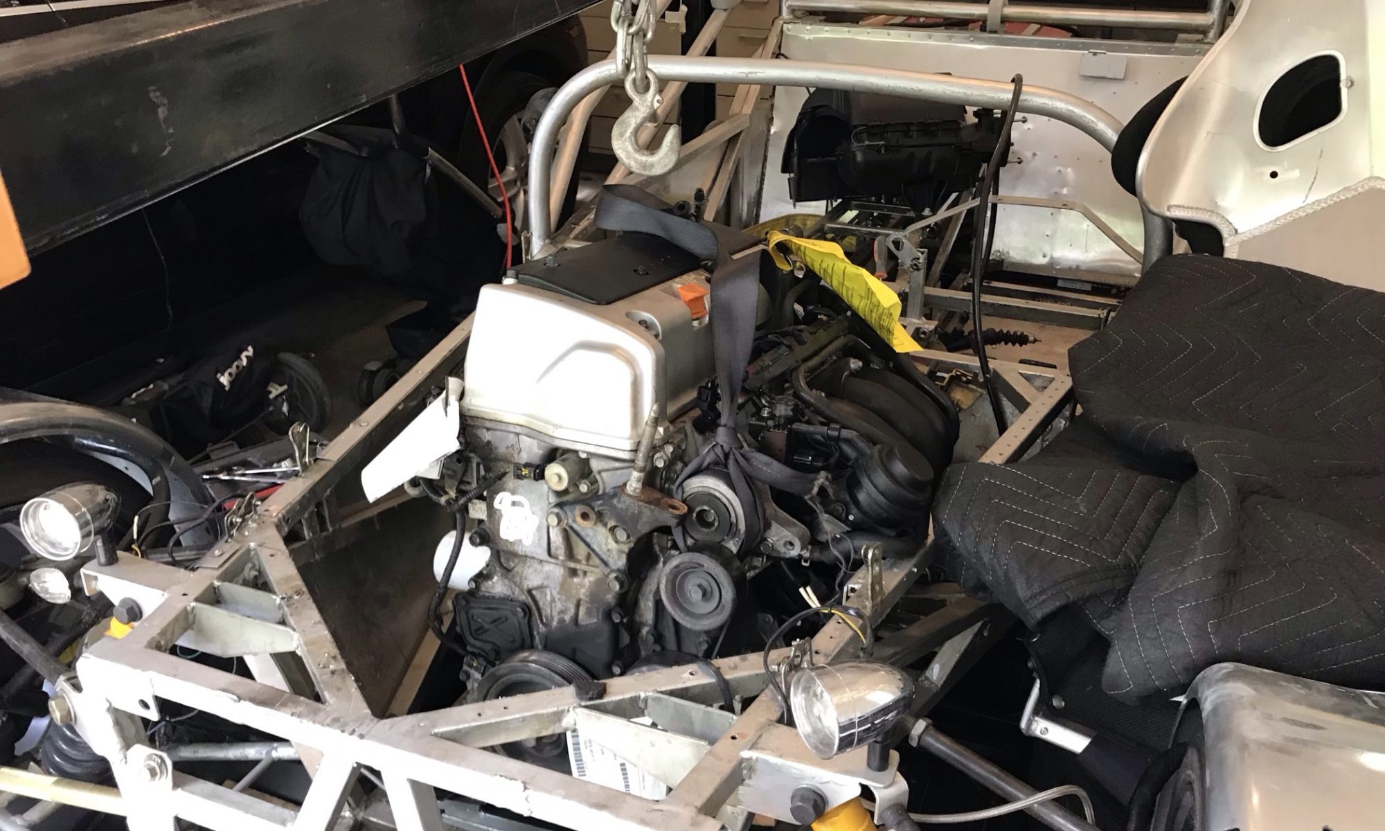
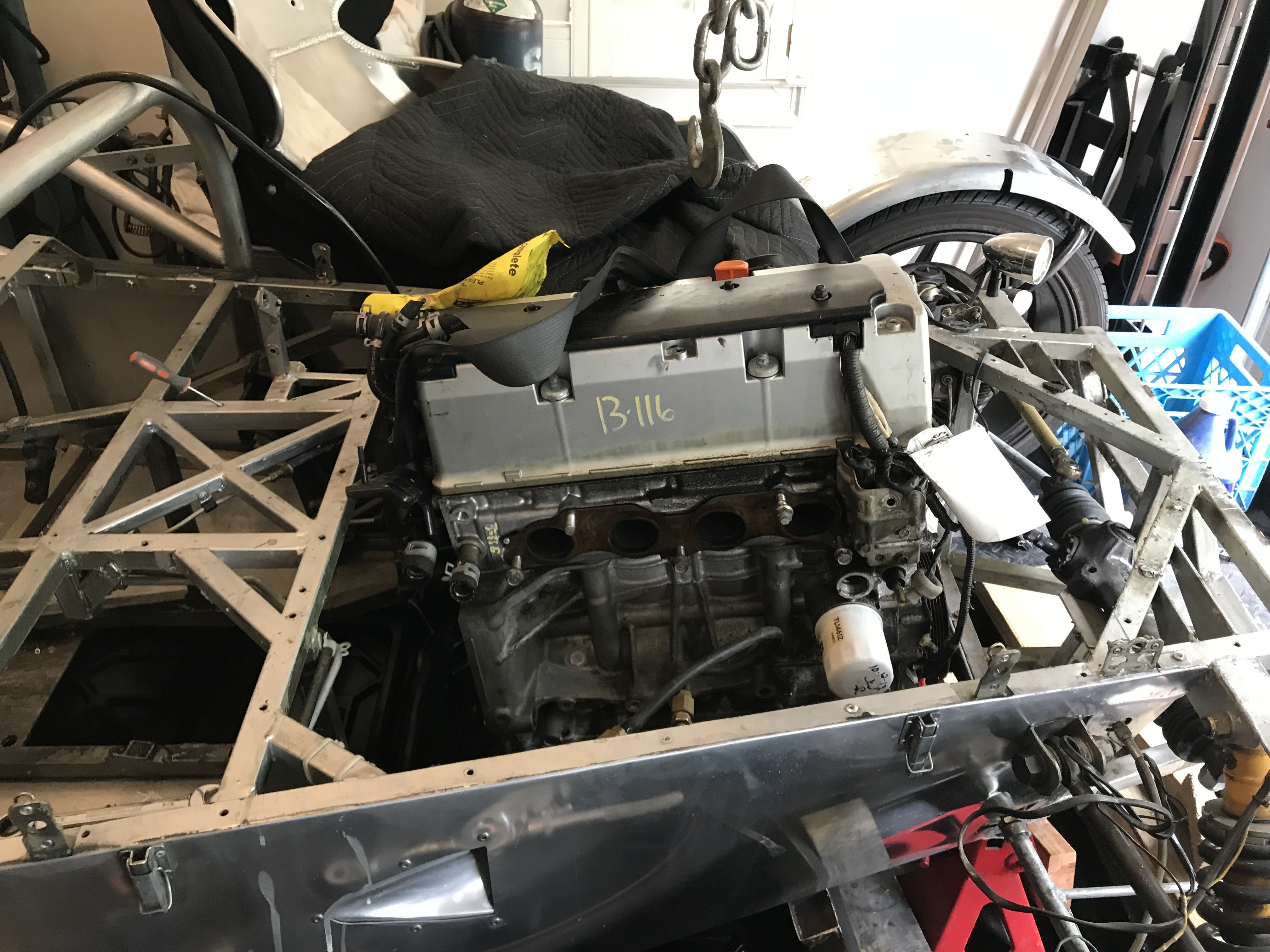
After that I managed to get a K20a3 motor to use as a mock up and potentially to use until I find a k20a2. The motor fits quite well and I’m optimistic it will work. Here is a picture of it just dropped into place and held by a 2×4

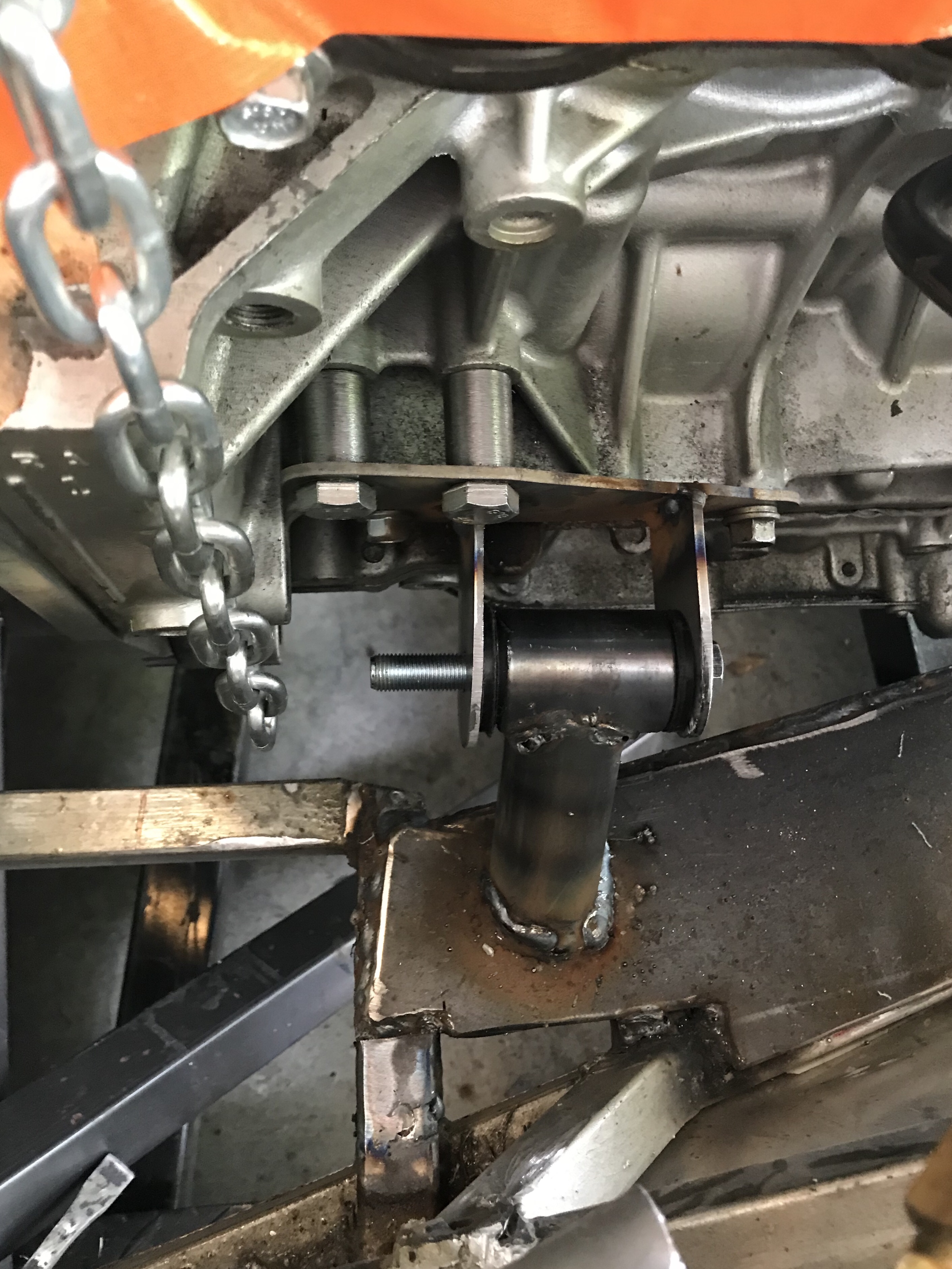
After having the engine and the transmission I needed to buy the adapter plate to marry them together. After the Ecotec problem I decided to stay as basic as possible until its weld ready. I bought just the plate and bolts and 3 days later they arrived.

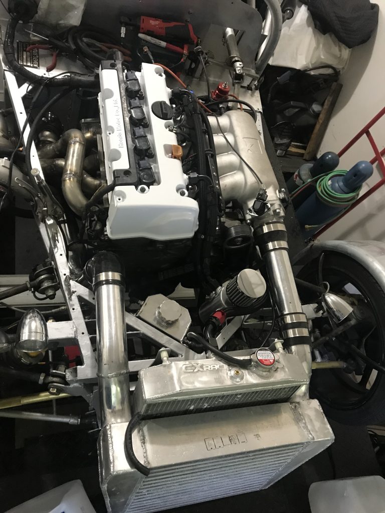
I pulled the motor out and gave it a good degreasing and the blew it off with compressed air. Then out came the adapter plate.

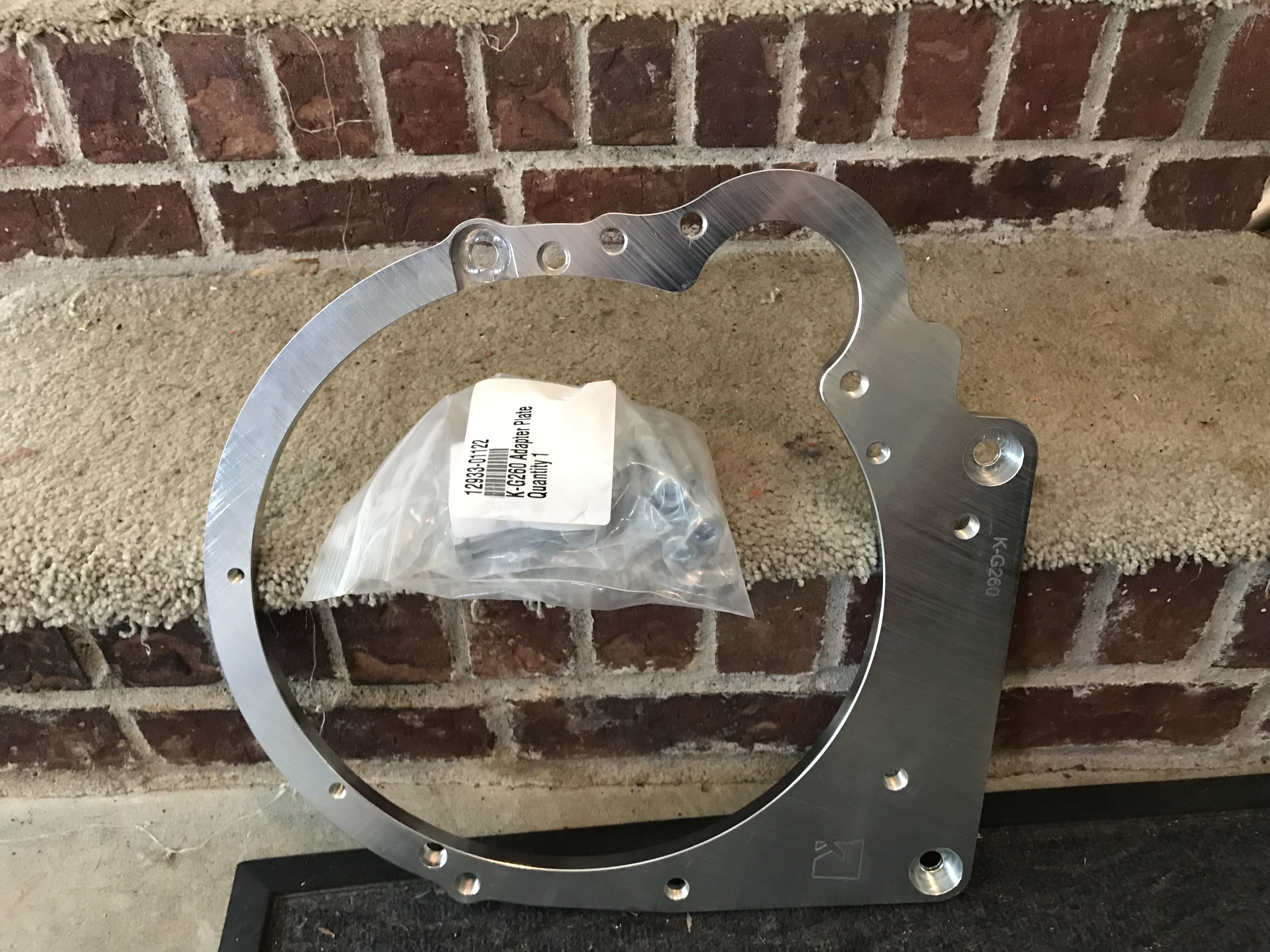
The quality is impeccable and my hopes of being able to “spend my way” to completion is still alive!

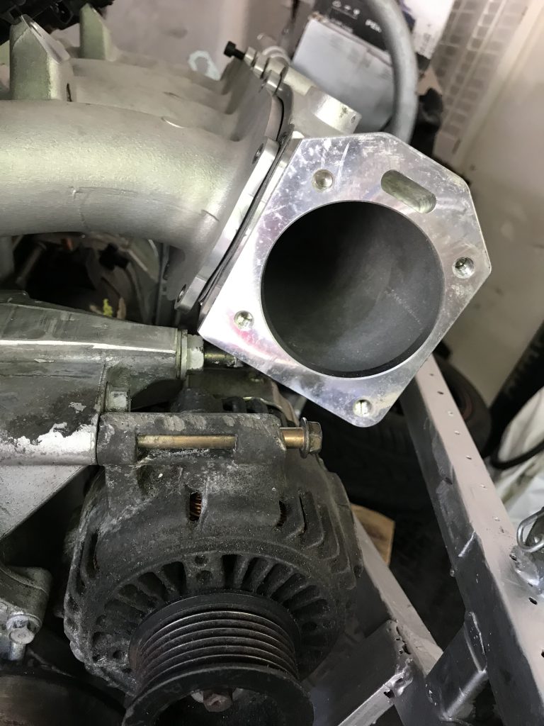
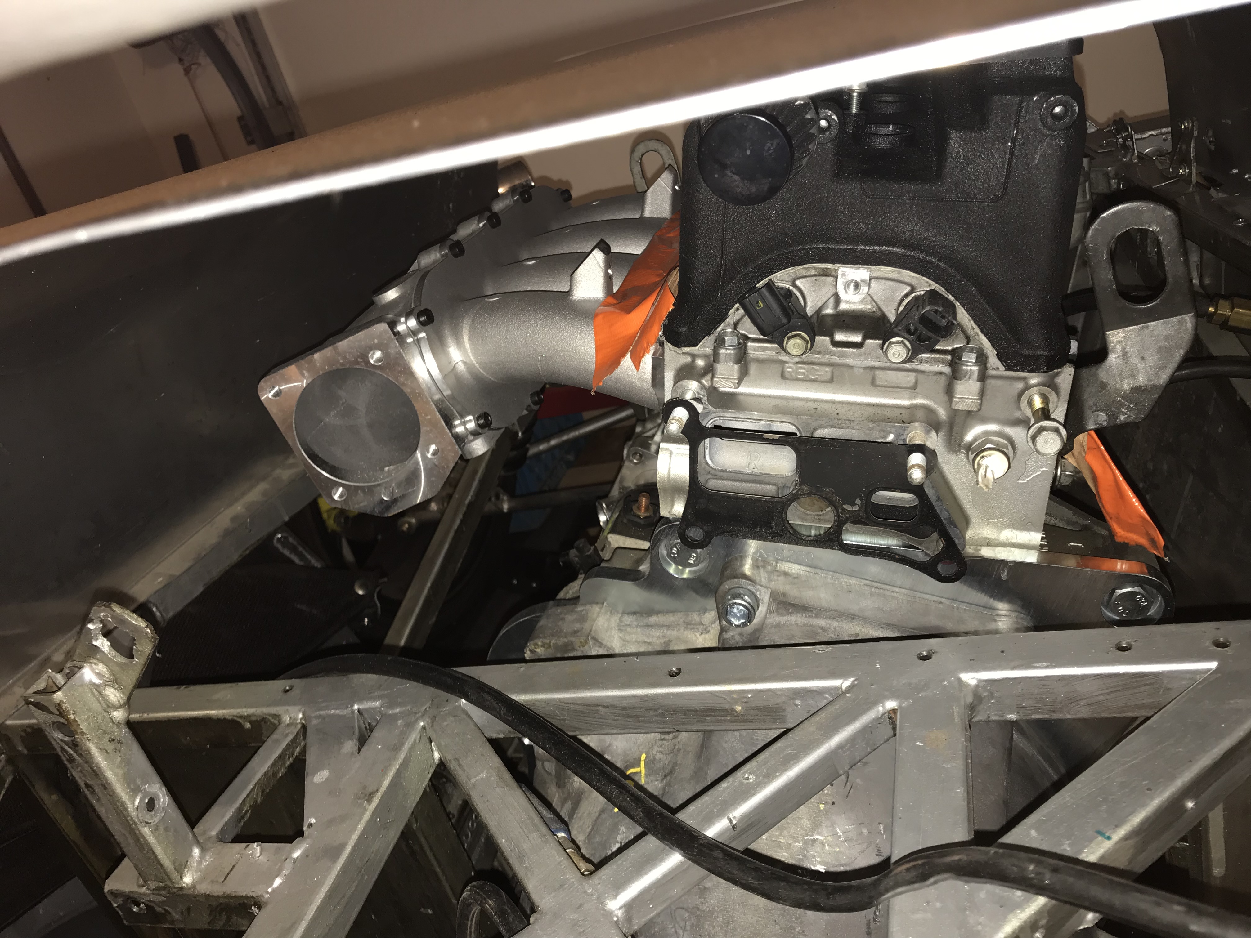
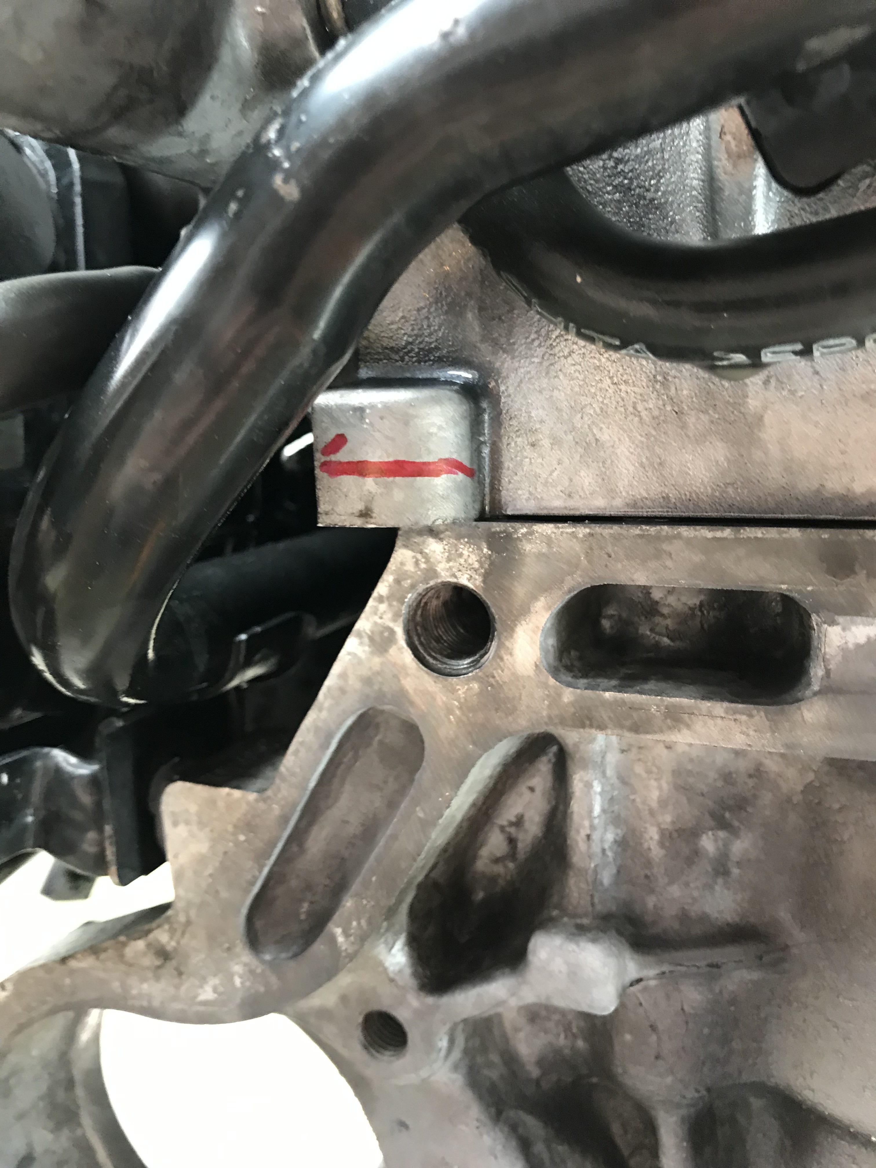
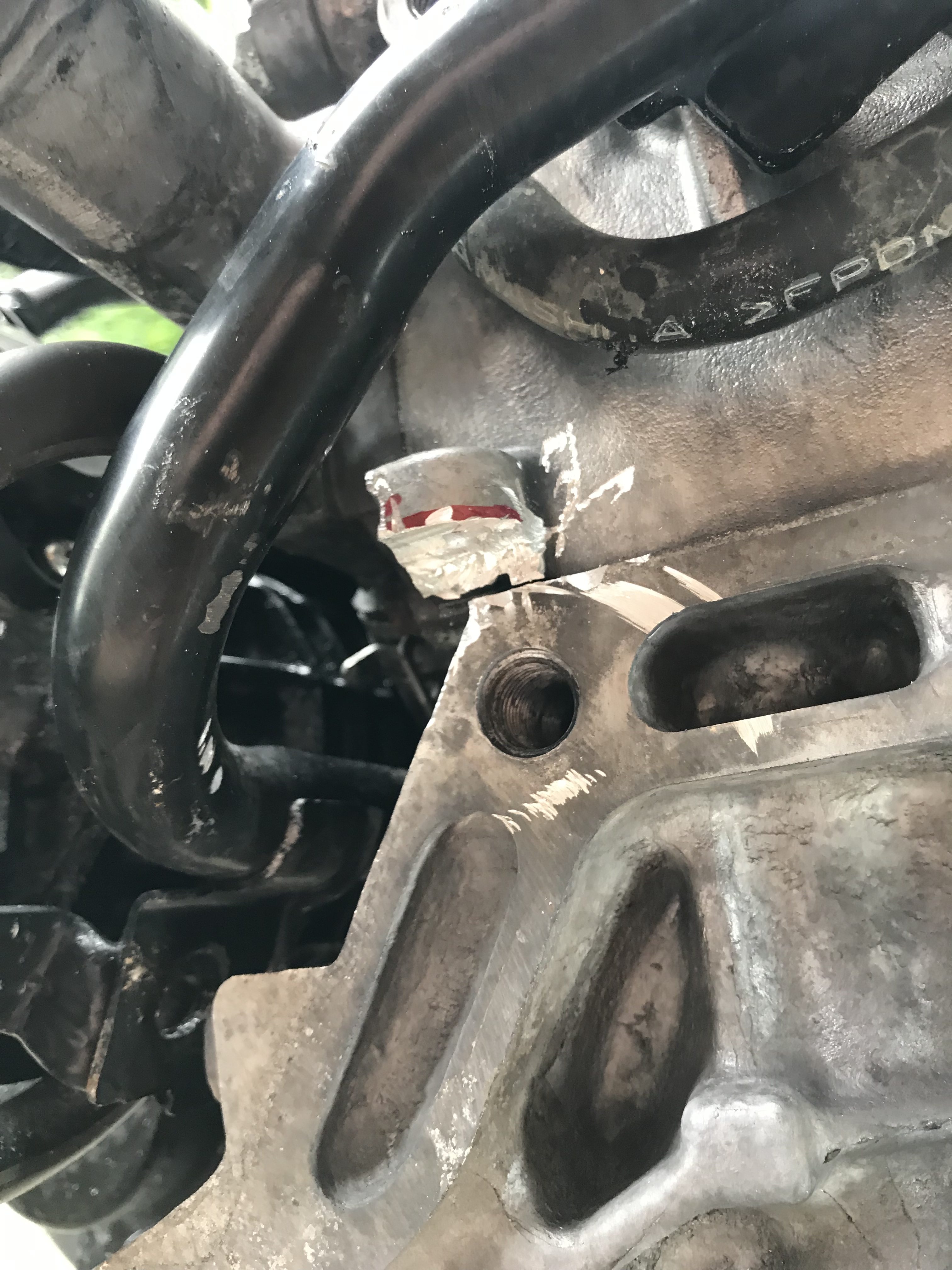
One small hiccup is that the a3 engine has a different head (the inferior one..) and so it had a fitment problem. Nothing a grinder couldn’t fix.

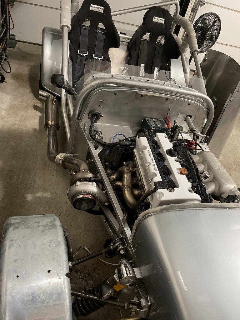
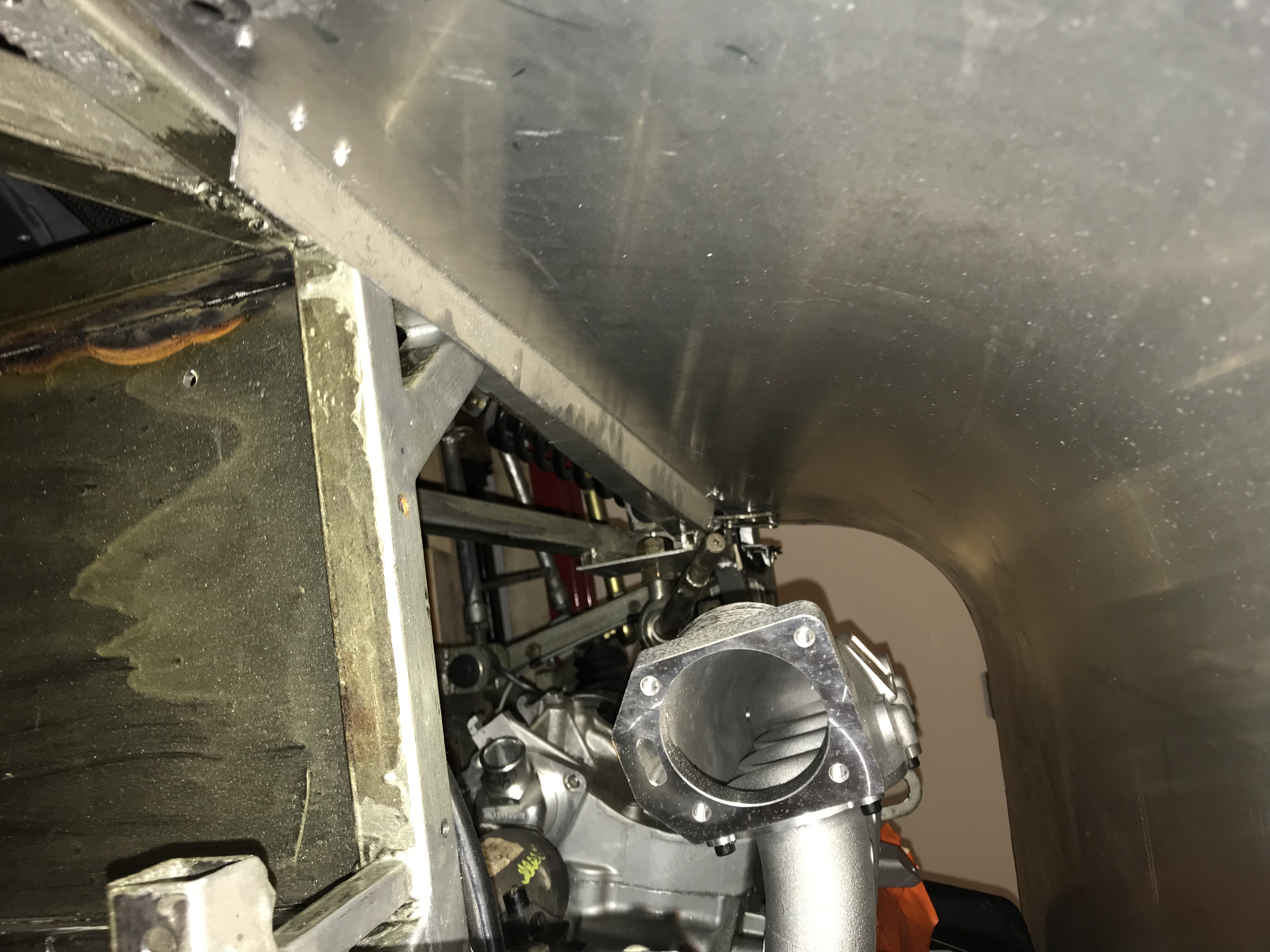
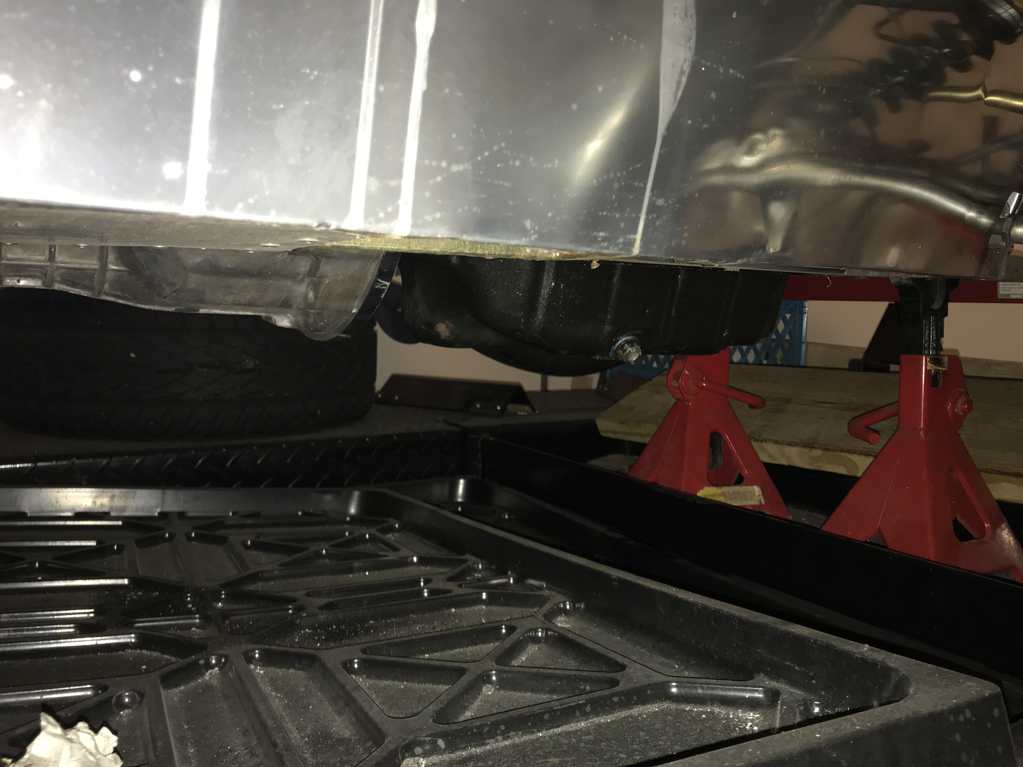
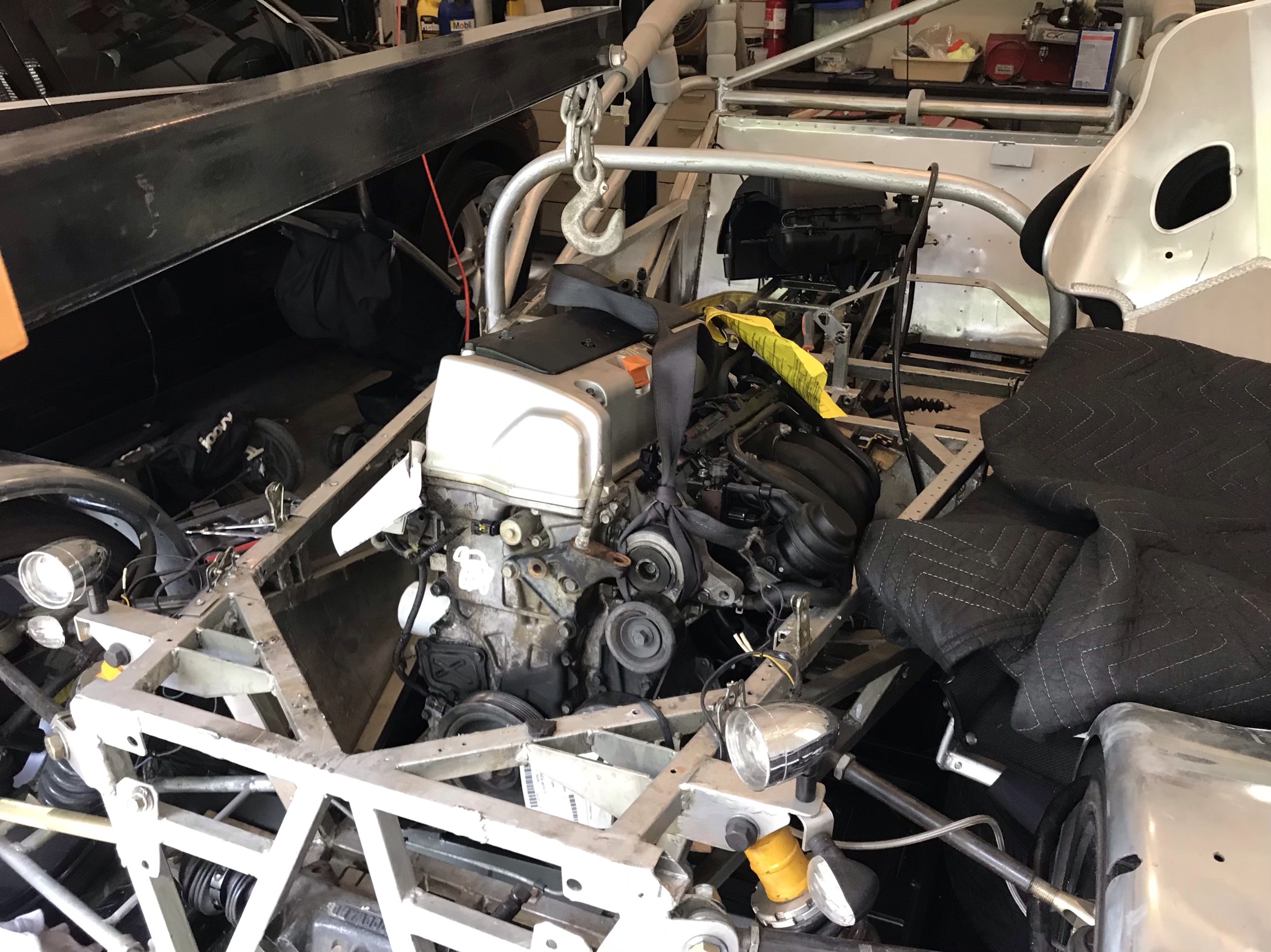
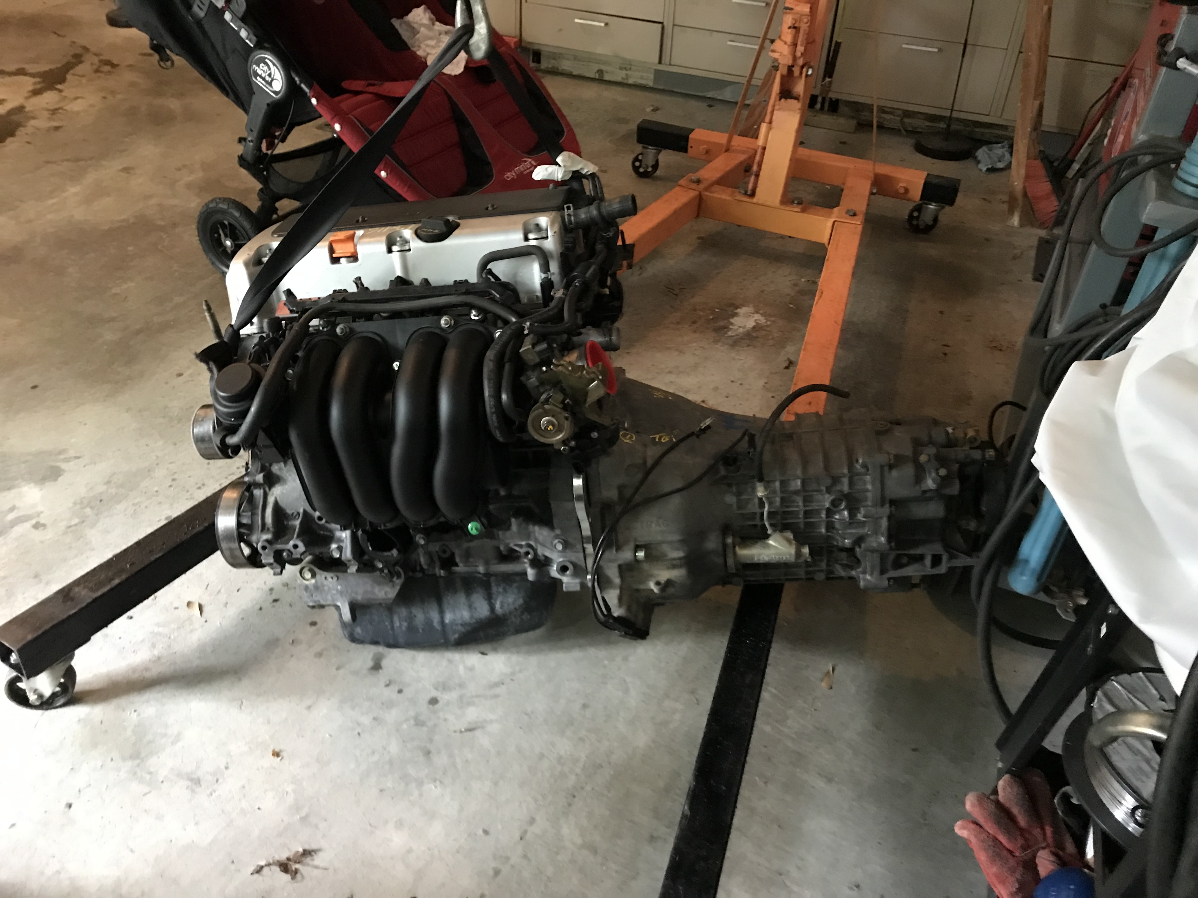
Time was running out and I had to go shower but that wouldn’t happen before bolting the two together with a minimal amount of bolts. Until next time this is my view when going to work:

Hoping to have the next update and some good news in about a week’s time!