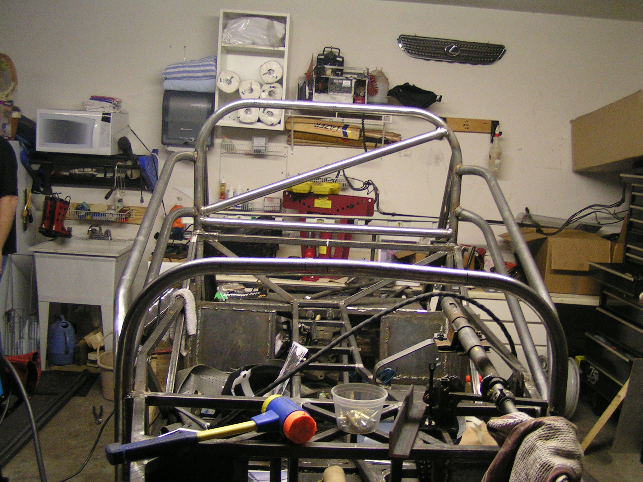
With the car being so low I knew I needed to have some form of protection from other vehicles. While the tall front cage is probably safer I like the look of the low front hoop and the “cocoon” it creates.
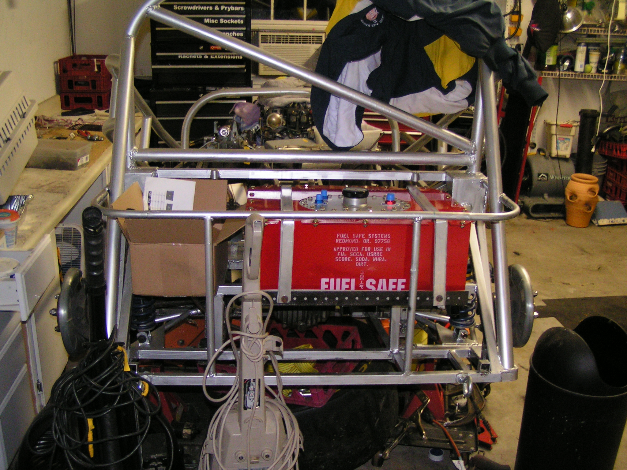
I wanted to have a low front hoop but side protection. There are some NASA cars running this type of cage and I really liked it. The strength it adds to the frame is a huge factor as well. Cage is built to SCCA Spec using 1.75″ DOM Tubing.
The front hoop mirrors the scuttle almost perfectly. The lower sections are attached via two points to the chassis and provides really strong side impact protection.
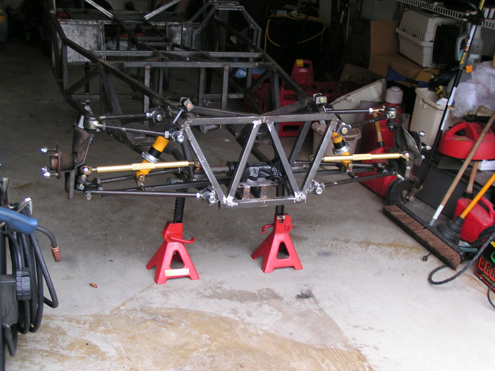
One critical piece of the project is the suspension. Depending on how much you know on the subject it could either be overly simplistic or incredibly complex.
Factors like dynamic toe, camber,caster and anti squat are all geometry concerns. Additionally spring rates and dampening round out the subject.
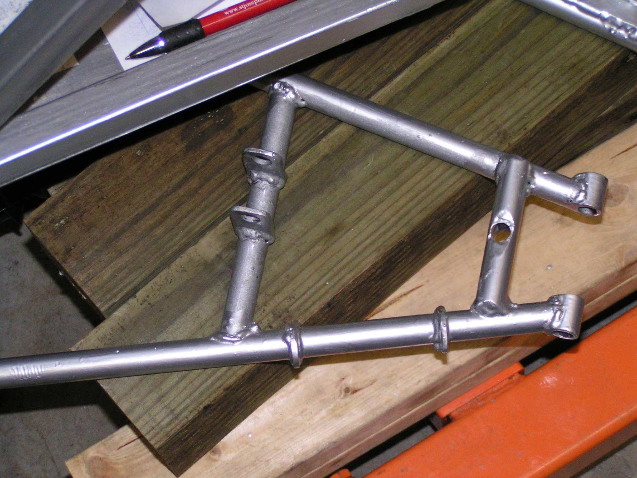
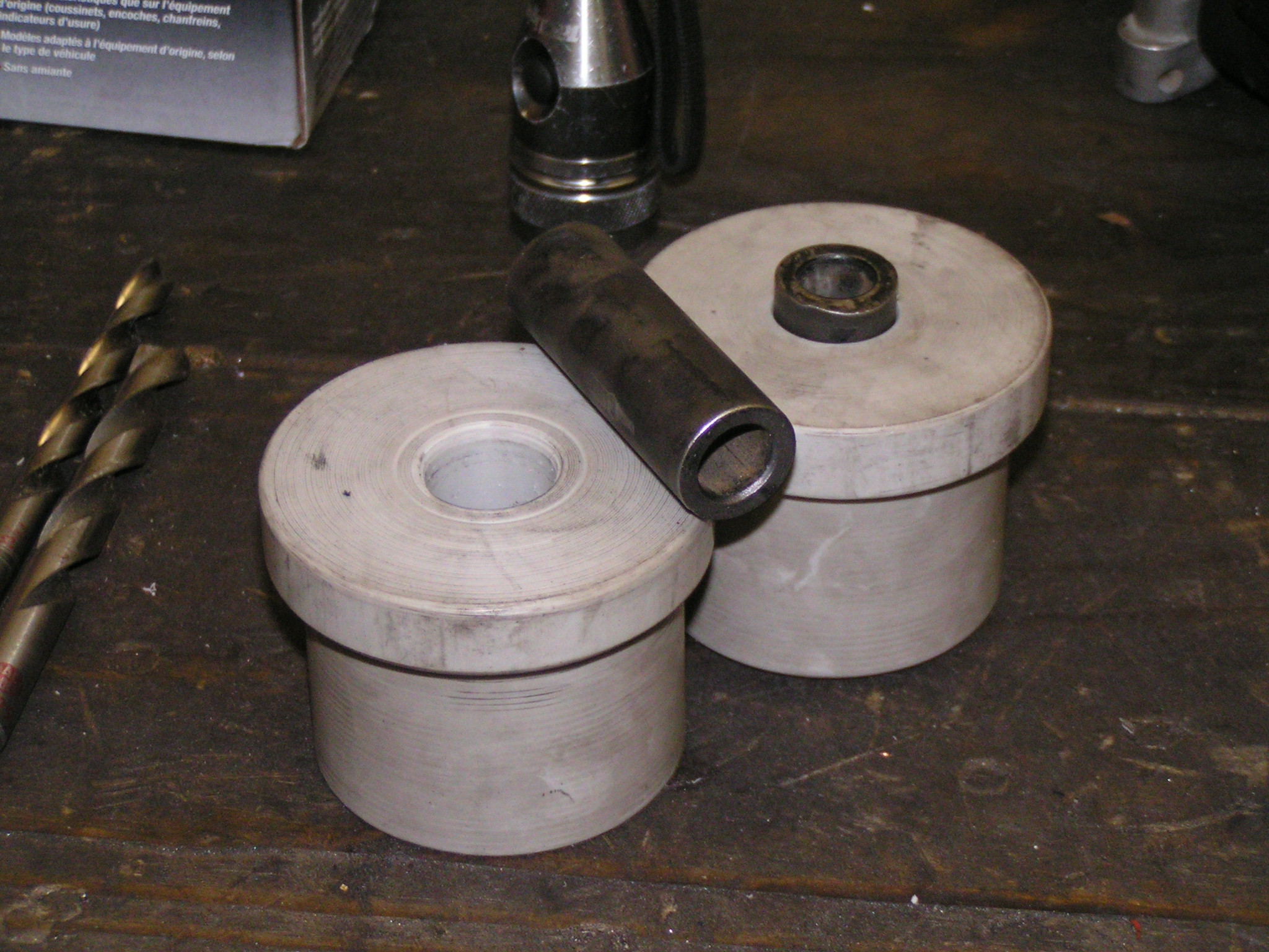
Front lower control arm
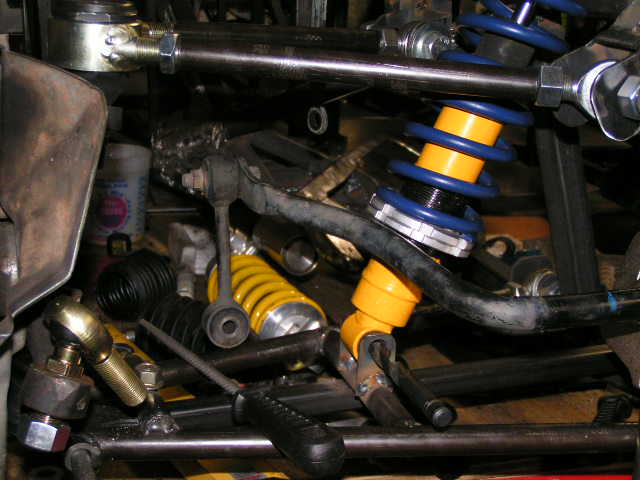
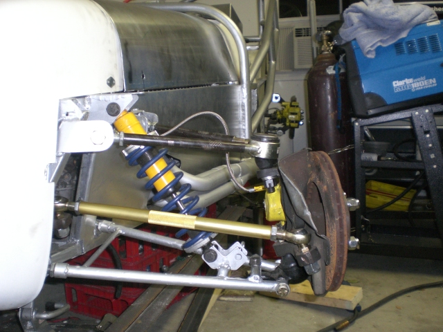
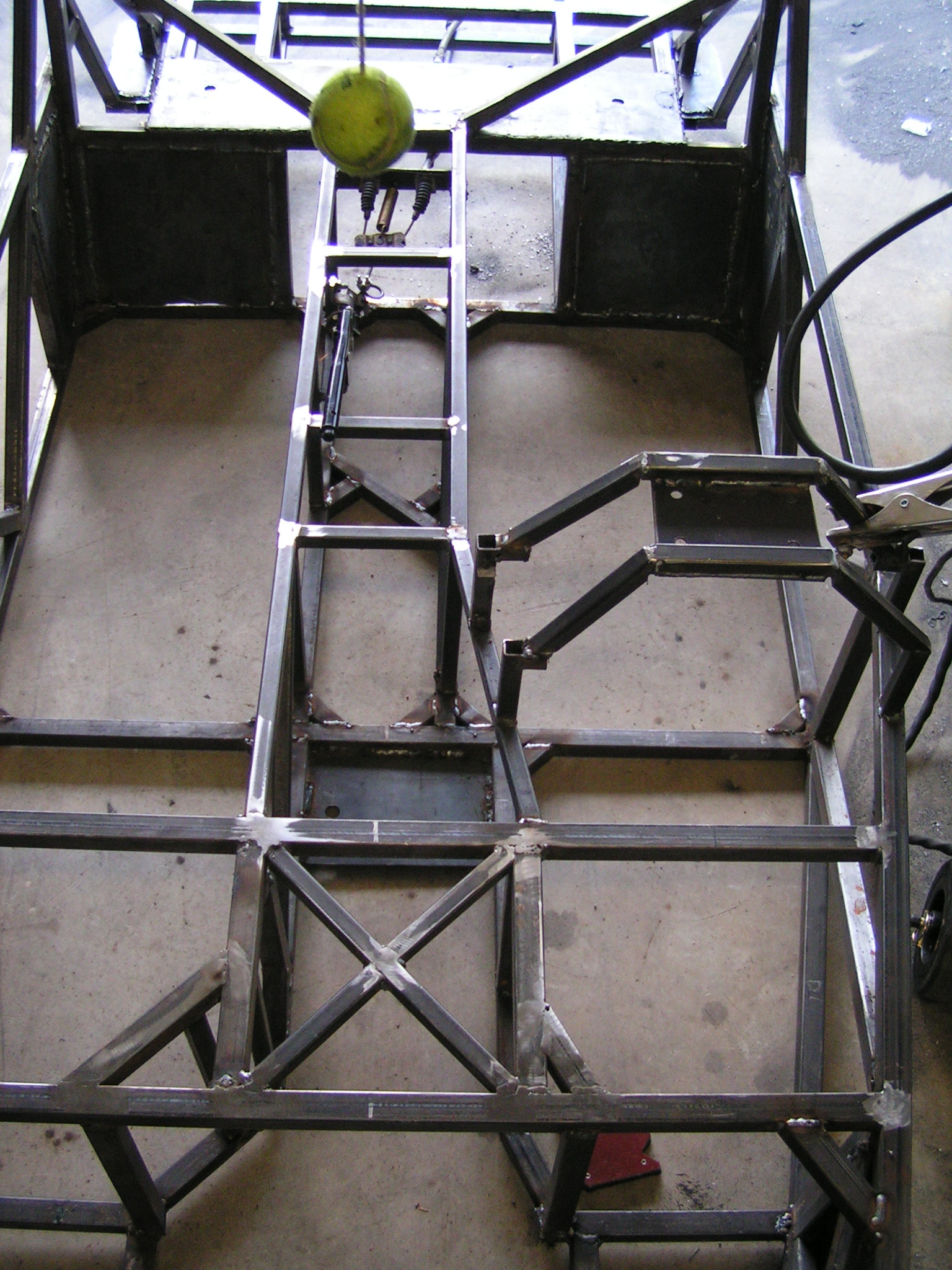
Initially I had the shocks set to a radical angle of 45 degrees. That was great in terms of fitment but required crazy spring rates since only half of it would be effective. I later built new mounts that moved the top of the shock out by 6″ and reduced the angle to something in the 20 degree range.
Original inboard upper shock mounting locationMock up of how the anti roll bar will fitEnd result.
We placed the vehicle on a laser mounted alignment rack when finished. The dimensions were absolutely amazing. The variation and setback differences were less than a production car typically exhibits. I couldn’t be happier with the suspension! It is absolutely fantastic with 300F and 450R springs
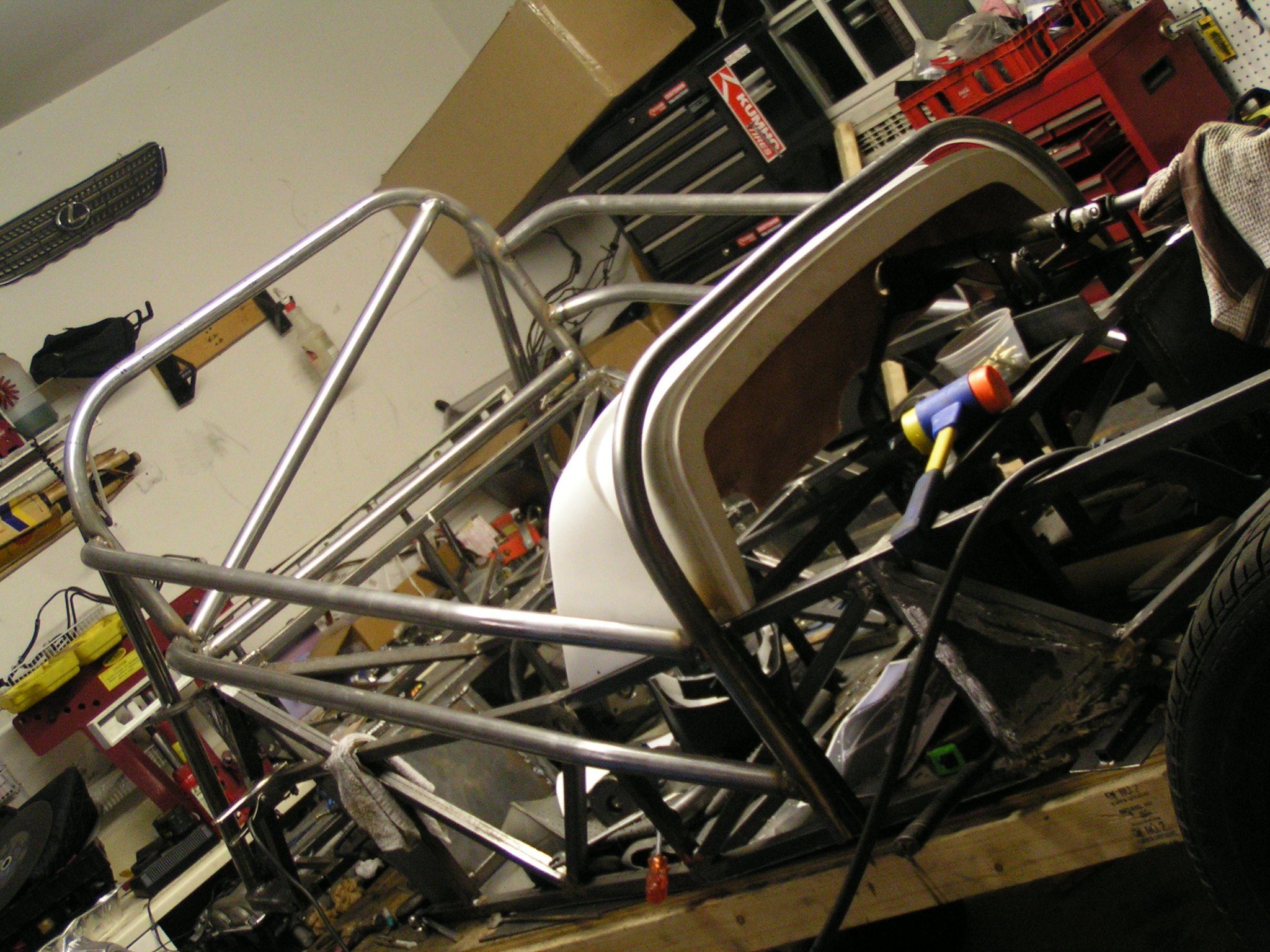
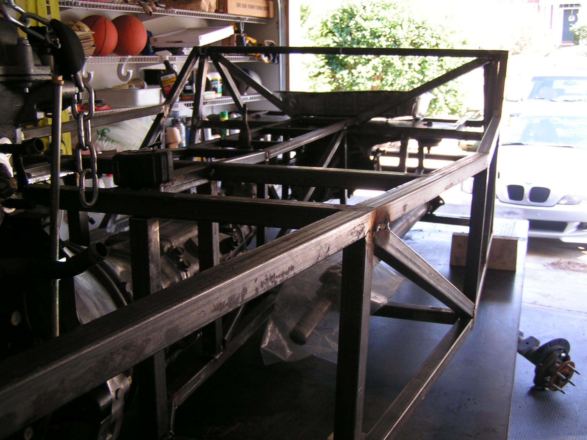
Here the chassis is starting to take solid shape. You can see a formed transmission tunnel and both pedal box areas. I would later come back and redo the steering column mount to avoid it hitting the scuttle
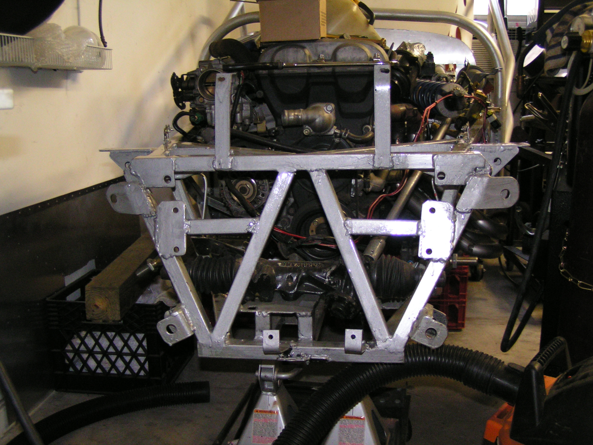
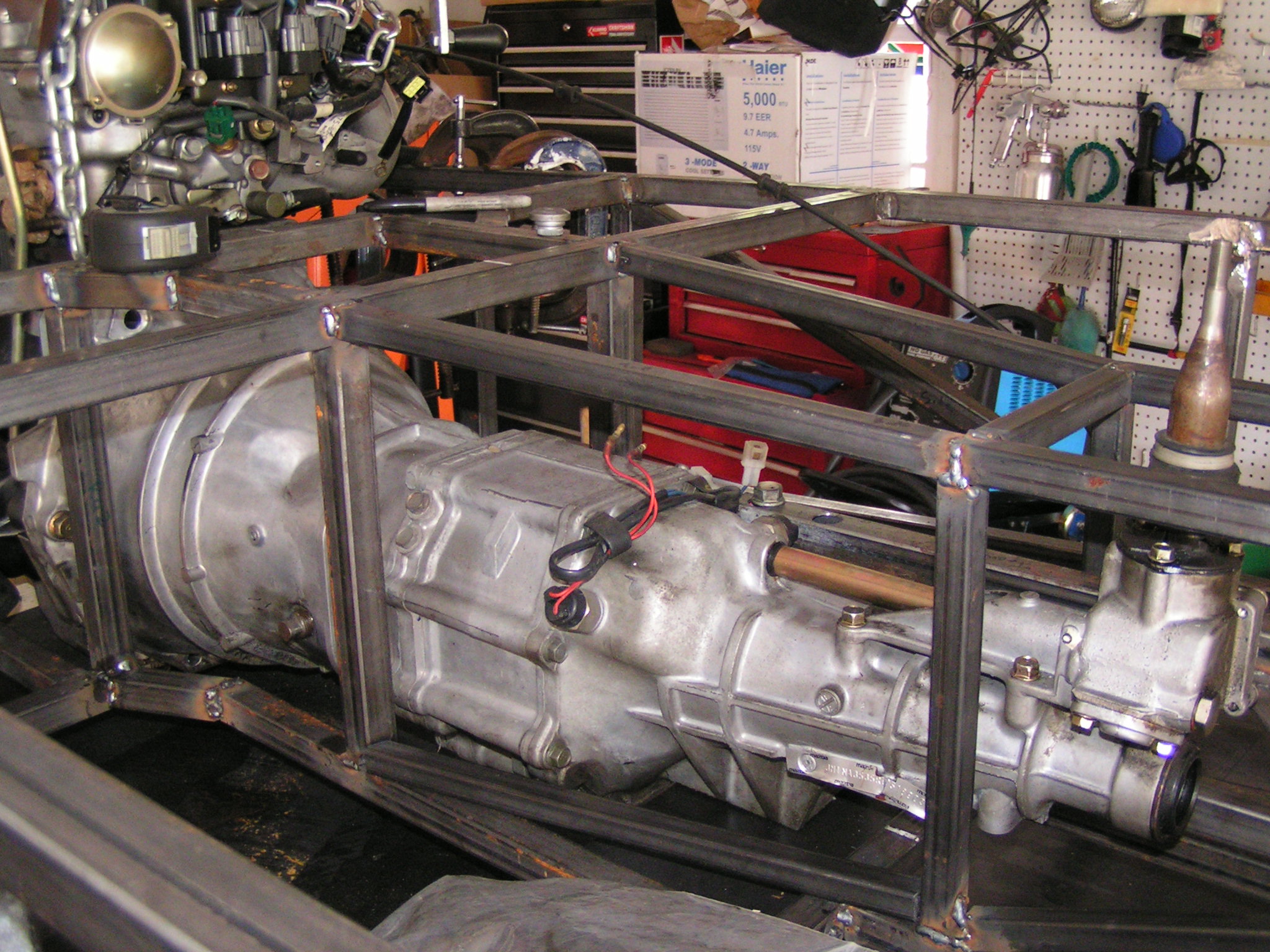
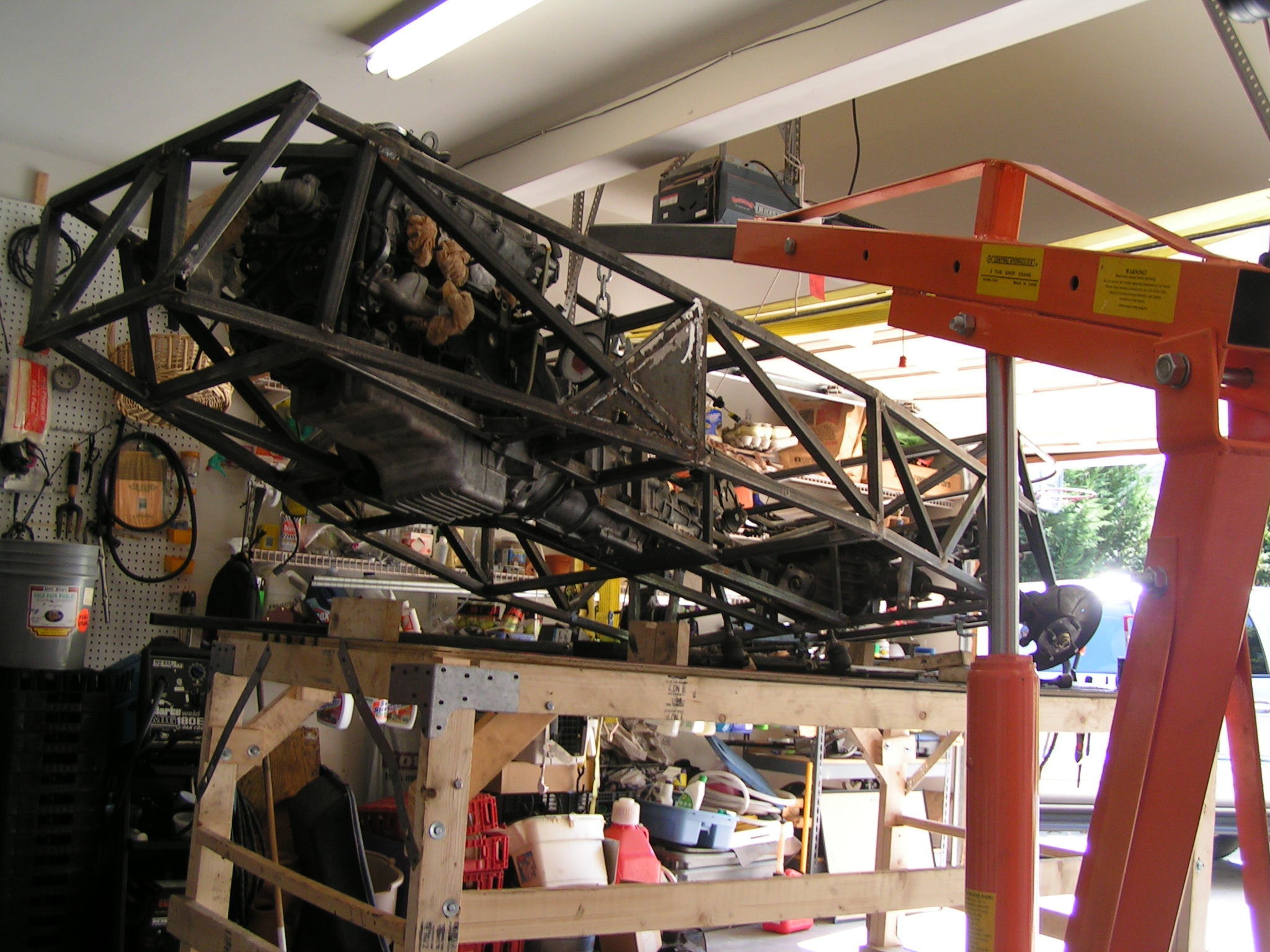
Transmission and engine test fit. The car is literally built around the engine and transmission. Optimizing around the engines height and shifter location.
Here you can see the first step in aligning the rear of the chassis using a laser level to set toe and camber.
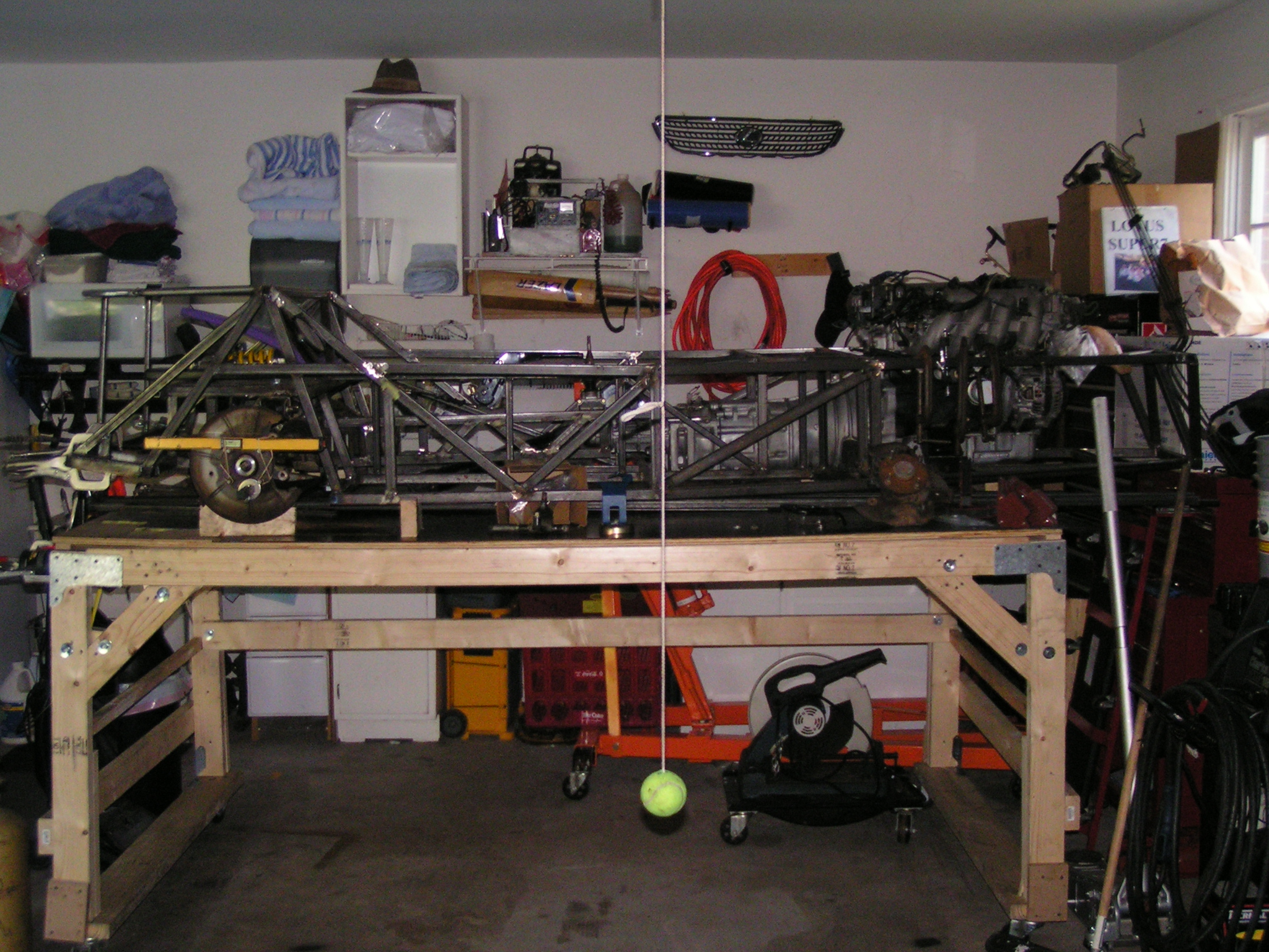
Yes – Chassis can fly! Here I remove it from the build table (I built that table so I could drive the front of a car under it) and started on the suspension.
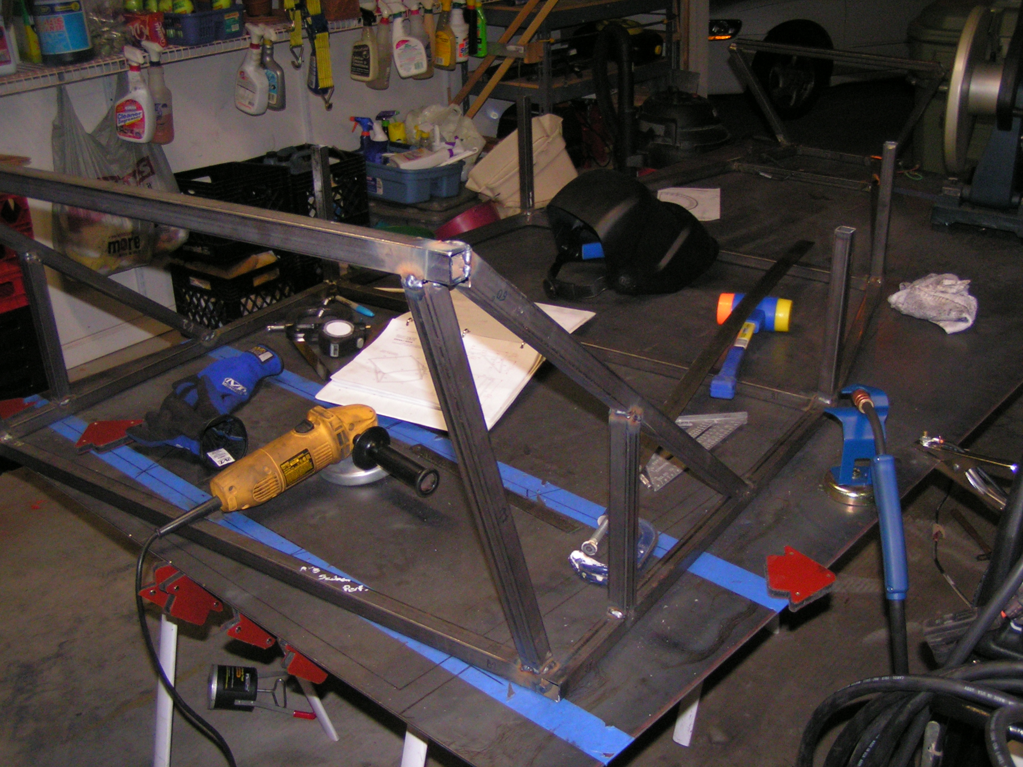
The first step in building the frame was to layout all of the pieces. First we (My Dad and myself) built the bottom layer and then started to add height. Here you can see the rear bulkhead being built.
Starting to lay out the Seating Area
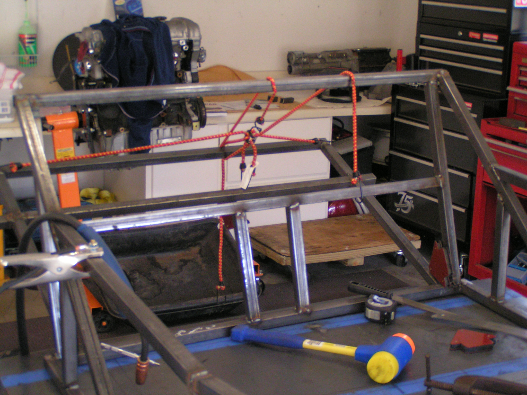
Rear section being mocked up (Bungee ties don’t build consistent angles.. in case you are wondering)
The area where the rear seats go Getting to the angle was difficult but the mess of bungee cables helped keep things in order.
Starting to look like a swing set…
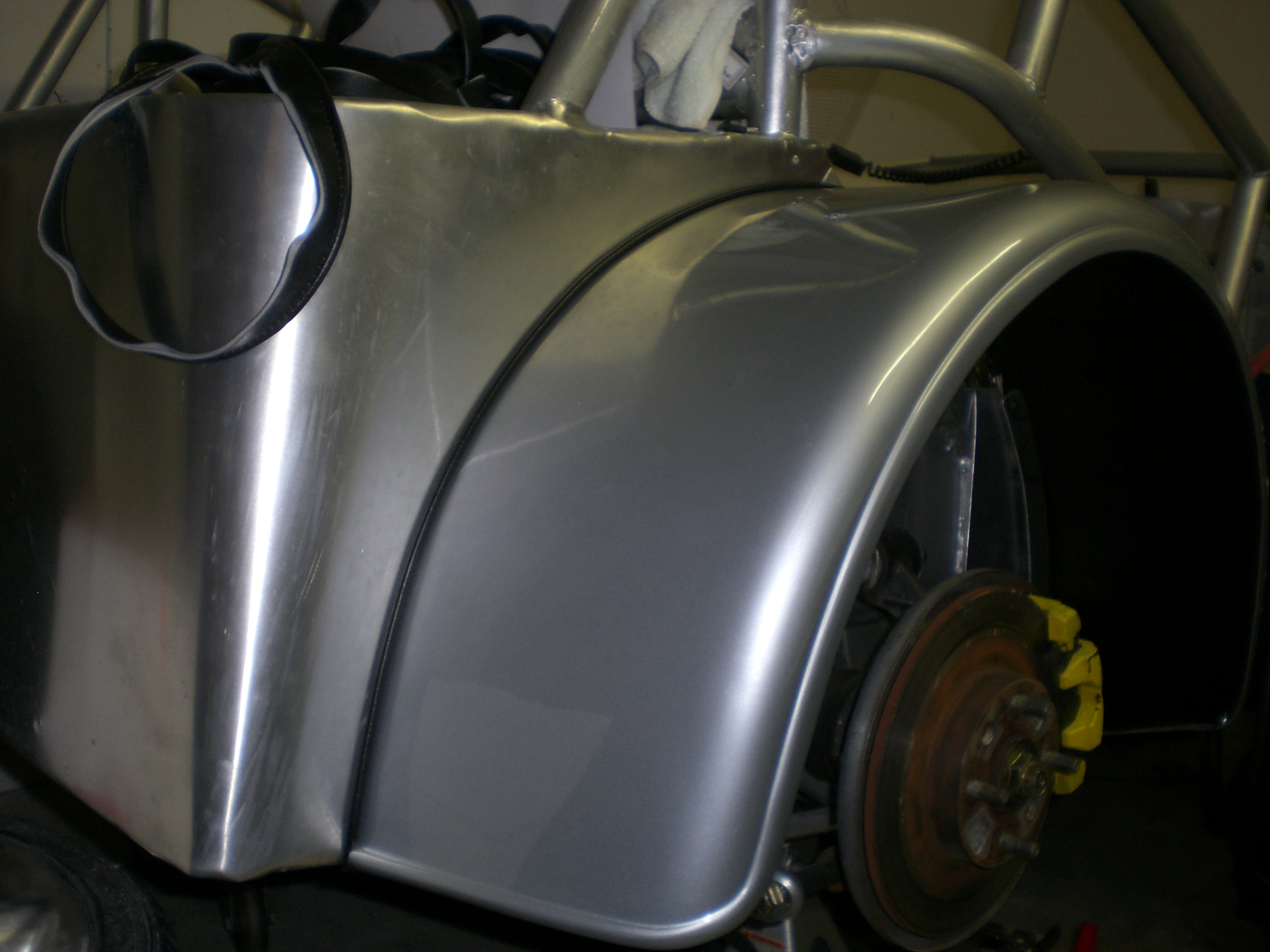
Finally we got to the point of having sides and needing to be ground down. It took a while but I believe in retrospect it was all well worth it.
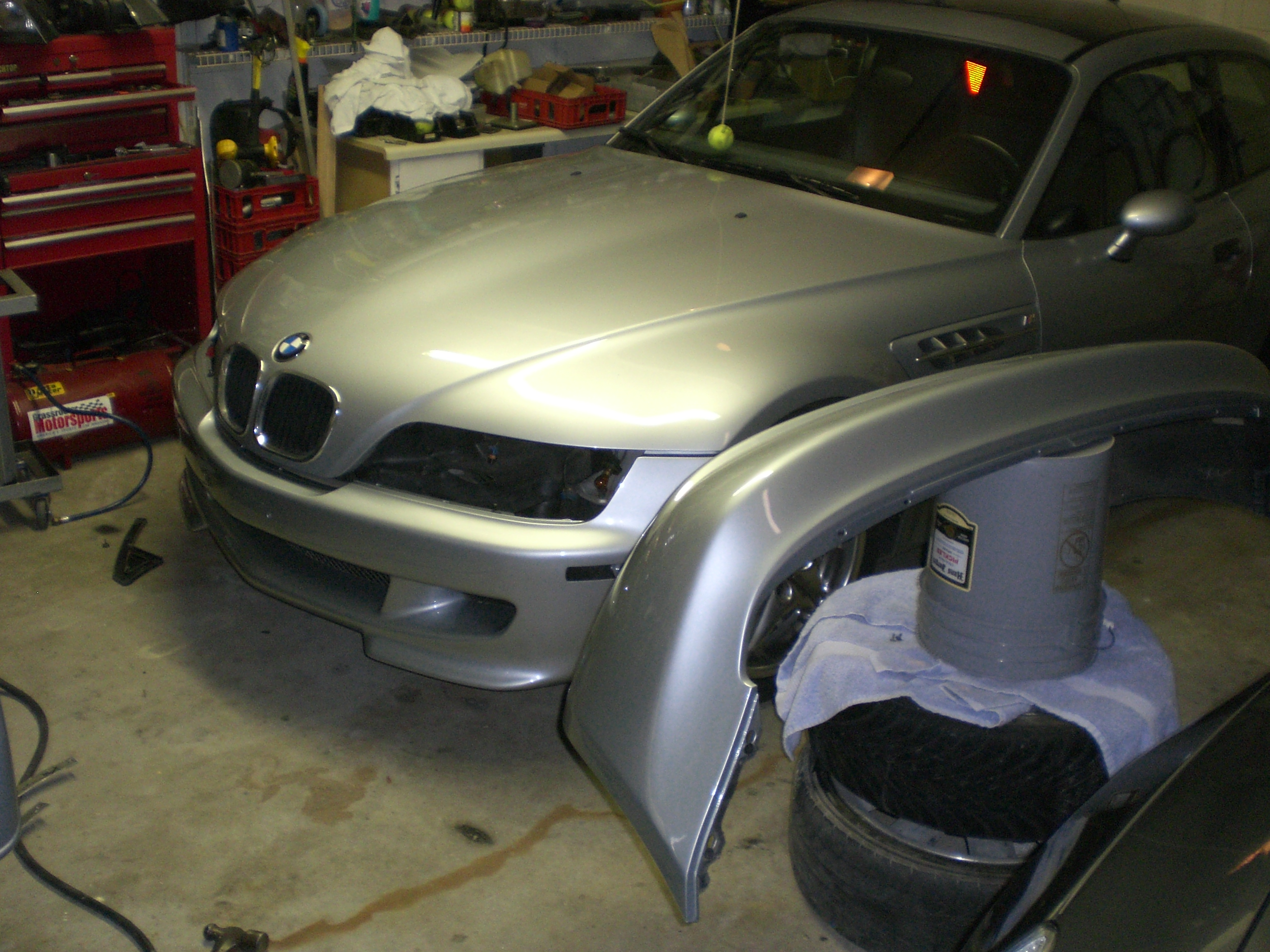
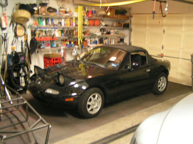
Once I decided I would start this project I realized I would need a donor. The North American favorite is the Mazda Miata because of the rear wheel drive configuration.
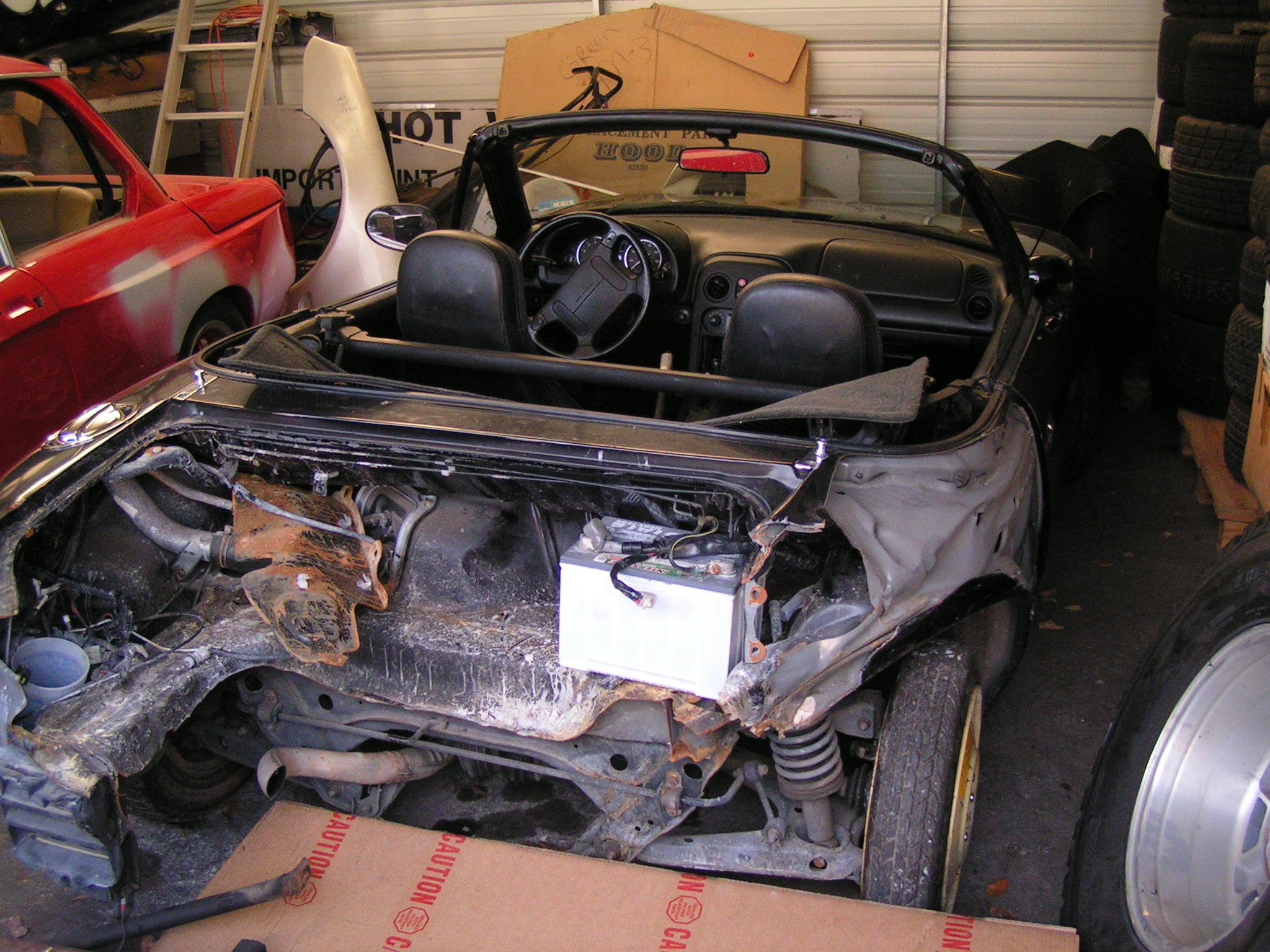
Talking to John Holt at HoltWheels and he mentioned he had this 94 with rear end damage. After discussing the terms we came to an agreement and he even delivered it.
What I landed on was a 94 Miata M with an open rear diff.
Driveline Donor.. in 2005
Reason it was a donor..
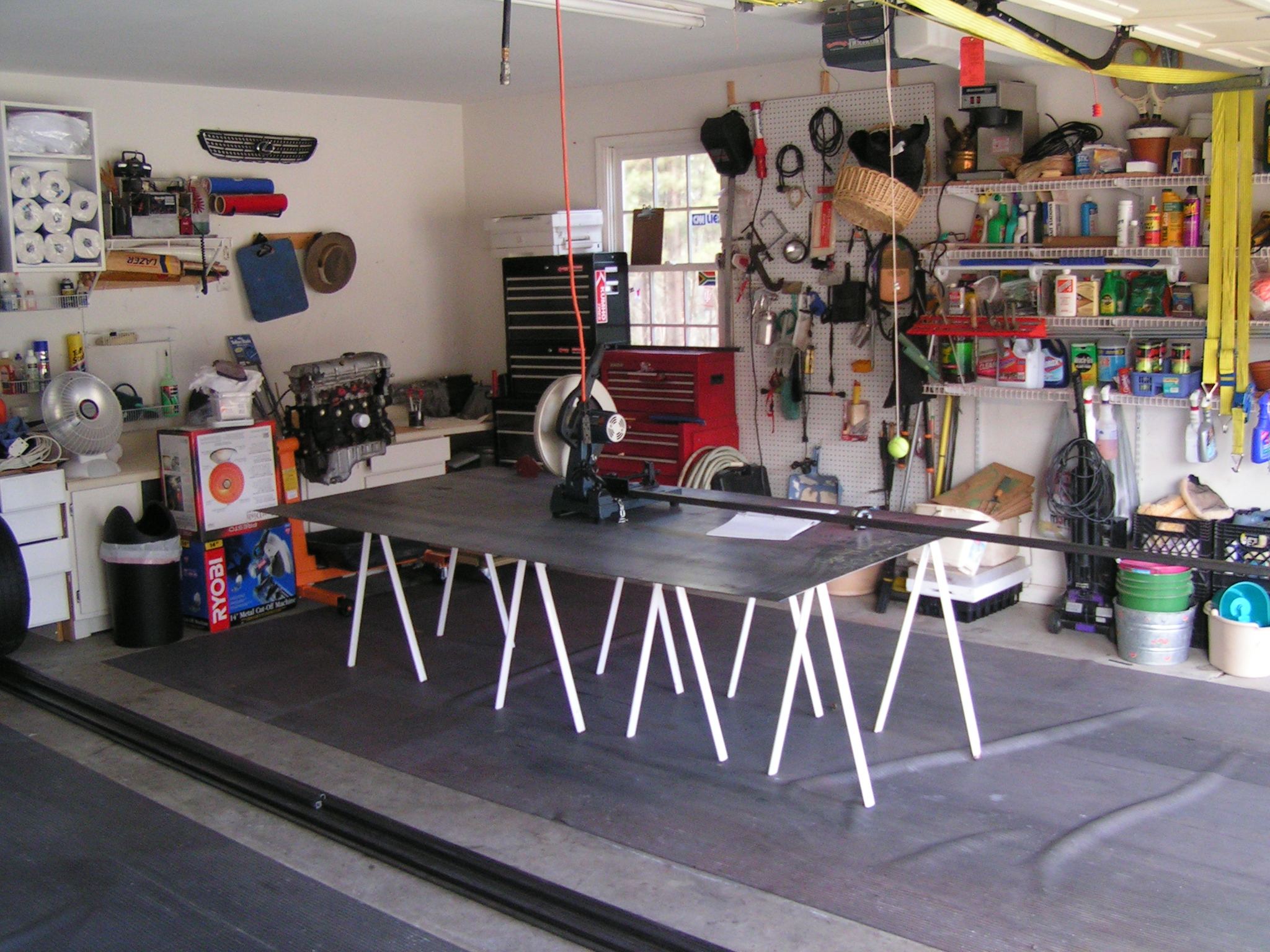
Build Table was needed and we used a piece of 1/4″ plate. It was “Flat enough” even though I see a good number of new builds with NASA level of engineering on their table. I bought an abrasive saw- I wouldn’t recommend it. New carbide saws or band saws are leaps ahead.
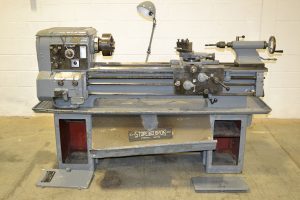
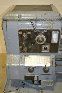
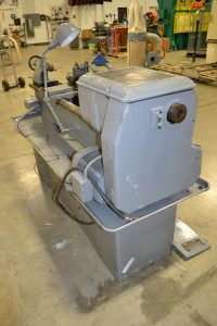
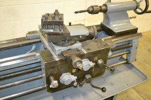
Shocking to believe that 2 years has flown by so quickly! I bought this lathe after it fell over on a fork lift while being unloaded. Needless to say it needed work.
Looking back at it now I don’t regret buying the lathe because it fell and needed some work -all of those repairs were relatively easy. What does concern me more is the footprint it occupies. This is a big boy!
There are still some handles that need to be made and the motor has been rewired for VFD. In terms of performance it is certainly a rock star!
In the near future I hope to provide some updates with where the machine is and what was needed to get there.
One of the most frustrating things I have encountered lately is a fortune of great posts being ruined by images no longer being available because of hosting changes. I told myself that I wanted to own all the pieces for future preservation!
I previously had a web server and it required a good bit of rework… rather than doing all that hard labor I just created this site!
About 13 years ago I started on the car you see below. There should be a good number of historic pages added to discuss the build and modifications.